FinePix S5800/S800 Service Manual
7
CONTENTS
Confidential: FUJIFILM Service Center Use Only
CONTENTS
1. General ....................................................... 1-1
1-1. Product specification ............................................1-1
1-2. Explanation of Terms ...........................................1-4
1-3. Names of External Components ..........................1-5
2. Disassembly ............................................... 2-1
2-1. Names of internal Components ...........................2-1
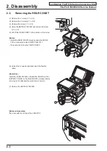
2-2. Removing the REAR CONST ..............................2-2
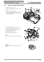
2-3. Disassembling the REAR CONST .......................2-3
2-4. Removing the LCD ..............................................2-4
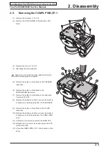
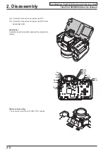
2-5. Removing the COMPL PWB,CP-1 ......................2-5
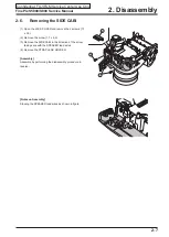
2-6. Removing the SIDE CABI ....................................2-7
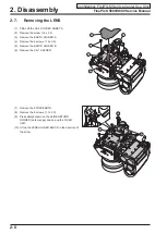
2-7. Removing the LENS ............................................2-8
2-8. Removing the FLASH UNIT and EVF UNIT ......2-10
2-8-1. Disassembling the FLASH UNIT .......... 2-11
2-8-2. Disassembling the ST HOLDER ..........2-13
2-9. Disassembling the LENS HOLDER TOP ...........2-15
2-10. Disassembling the CABI FRONT .......................2-17
2-11. Affixing locations for SPACERS and
COMPL PWB,CP-1 ..............................2-18
2-11-3. Attaching the SHEET and SPACER
to the LCD HOLDER ............................2-19
LCD SPACER A and
LCD SPACER C to the LCD .................2-20
2-11-5. Attaching the LCD SPACER B to the
CABI BACK ..........................................2-21
2-11-6. Attaching the LENS SPACER and
LCD SPACER B to the
LENS HOLDER TOP ............................2-21
3. Schematics ................................................. 3-1
3-1. Description of CCD circuit operation ....................3-1
3-1-1. Overview ................................................3-1
3-1-2. IC931 (CCD imager) ..............................3-1
3-1-3. IC901 (V driver) and IC905 (H driver) ....3-2
3-1-4. IC905 (CDS, AGC and A/D converter) ...3-2
3-2. Description of CP1 circuit operation ....................3-2
3-2-1. Circuit Description ..................................3-2
3-2-2. Outline of Operation ...............................3-3
3-2-3. LCD Block ..............................................3-3
3-2-4. EVF Block ..............................................3-3
3-2-5. Lens Drive Block ....................................3-3
3-3. Description of PWA Power Circuit Operation .......3-4
3-3-1. Overview ................................................3-4
3-4. Description of ST1 flash circuit operation ............3-5
3-5. Description of SYA circuit operation .....................3-6
3-5-1. Configuration and Functions ..................3-6
3-5-2. Internal Communications Paths .............3-7
3-5-3. Key Operations ......................................3-7
3-5-4. Power Supply Control ............................3-8
3-6. Block Diagram .....................................................3-9
3-7. Overall connection Diagram ..............................3-10
3-8. Circuit Diagrams ................................................ 3-11
3-8-1. CA1 BLOCK ......................................... 3-11
3-8-2. CA2 BLOCK .........................................3-12
3-8-3. CCD BLOCK ........................................3-13
3-8-4. CP1 BLOCK (DMA) ..............................3-14
3-8-5. CP1 BLOCK (PWA) .............................3-15
3-8-6. CP1 BLOCK (STA) ...............................3-16
3-8-7. CP1 BLOCK (SYA) ...............................3-17
3-8-8. CP1 BLOCK (TCA) ..............................3-18
3-8-9. FLASH BLOCK ....................................3-19
3-8-10. MAIN/LCD DRIVER BLOCK ................3-20
3-8-11. POWER BLOCK ..................................3-21
3-8-12. SYSTEM CONTROL BLOCK ...............3-22
3-8-13. LENS BLOCK .......................................3-23
3-8-14. PW1 BLOCK ........................................3-24
3-8-15. TB1 BLOCK .........................................3-25
3-8-16. TB2 BLOCK .........................................3-26
3-9. Mounted Parts Diagrams ...................................3-27
3-9-1. CA1 PWB ASSY ...................................3-27
3-9-2. CA2 PWB ASSY ...................................3-28
3-9-3. TB1 PWB ASSY ...................................3-29
3-9-4. TB2 PWB ASSY ...................................3-29
3-9-5. MAIN PWB ASSY .................................3-31


