FinePix S5800/S800 Service Manual
3-6
3. Schematics
Confidential: FUJIFILM Service Center Use Only
3-5.
Description of SYA circuit operation
3-5-1.
Configuration and Functions
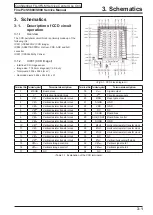
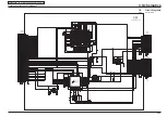
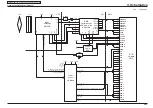
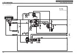
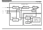
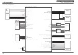
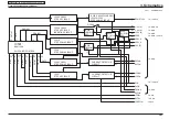
Refer to the block diagram for the overall configuration of the SYA block. The SYA block consists primarily of an 8-bit
microprocessor (IC301).The functions of the 8-bit microprocessor include: 1. Control key input, 2. Clock management and
backup; 3. Power ON/OFF; and 4. Flash charging control.
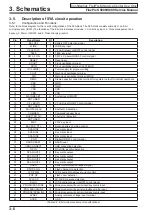
Pin
Signal Name
I/O
Description
1
BAT OFF
I
Battery OFF detection signal
2
WIDE
I
WIDE key input
3
VF. LED (G)
O
VF LED (green) ON/OFF control signal
4
TELE
I
TELE key input
5
SW 3.2 ON
O
SW 3.2 V power ON/OFF control signal
6
RESET
I
Reset input
7
XCOUT
O
Clock oscillation terminal
8
XCIN
I
Clock oscillation terminal (32.768kHz)
9
IC (FLMD0)
-
Power supply for program writing
10
XOUT
O
Main clock oscillation terminal
11
XIN
I
Main clock oscillation terminal (4MHz)
12
REGC
O
Stable-capacity connection terminal for regulator output for internal operations
13
VSS
-
GND
14
VSS
-
GND
15
VDD
-
VDD
16
VDD
-
VDD
17
MAIN RESET
O
System reset (MRST)
18
NOT USED
-
-
19
VF. LED (R)
O
VF LED (red) ON/OFF control signal
20
NOT USED
-
-
21
SHUTTER 2nd
I
Shutter 2nd detection
22
COMREQ
I
Command request input
23
SHUTTER 1st
I
Shutter 1st detection
24
NOT USED
-
-
25
PLAY
I
PLAY key input
26
BACKUP_CTL
O
Backup battery charging control
27
SCAN IN2
I
Key matrix input
28
SCAN IN1
I
Key matrix input
29
SCAN IN0
I
Key matrix input
30
P ON
O
Digital ON/OFF control signal
31
NAND RESET
O
NAND reset
32
USB CONNECT
I
USB connection detection
33
DC IN
I
DC JACK insertion detection
34
SCAN OUT0
O
Key matrix output
35
SCAN OUT1
O
Key matrix output
36
SCAN OUT2
O
Key matrix output
37
SCAN OUT3
O
Key matrix output
38
SREQ
I
Serial communication request signal
39
STOP CHG
I
Flash charge stop detection
40
LCD PWM
O
LCD backlight brightness current control
41
POP UP
I
Flash cover detection
42
AV JACK
I
AV JACK presence detection
43
BL ON
O
LCD backlight power ON/OFF control signal
44
PRG SO/SCAN IN3
O/I Microprocessor write serial input/key matrix input
45
PRG SI/SCAN IN4
I/I
Microprocessor write serial output/key matrix input
46
PRG SCK/SCAN IN5
O/I Microprocessor write serial clock/key matrix input
47
AVREF
-
Analog reference voltage input terminal
48
AVSS
-
GND
<Table 3-2. 8-bit microprocessor port specifications>


