background image

2

FinePix6800Zoom(U/E/EG)  SCHEMATICS

1.Check the area of your repair for unsoldered or

poorly soldered connections. Check the entire
board surface for solder splasher and bridges.

2. Check the interboard wiring to ensure that no

wires are ìpinchedî or contact high-wattage re-
sistors.

3. Look for unauthorized replacement parts, par-

ticularly transistors, that were installed during a
previous repair. Point them out to the customer
and recommend their replacement.

4. Look for parts which, though functioning, show

obvious signs of deterioration. Point them out to
the customer and recommend their replacement.

5. Check the B + voltage to see it is at the values

specified.

6. Make leakage - current measurements to deter-

mine that exposed parts are acceptably insulated
from the supply circuit before returning the product
to the customer.

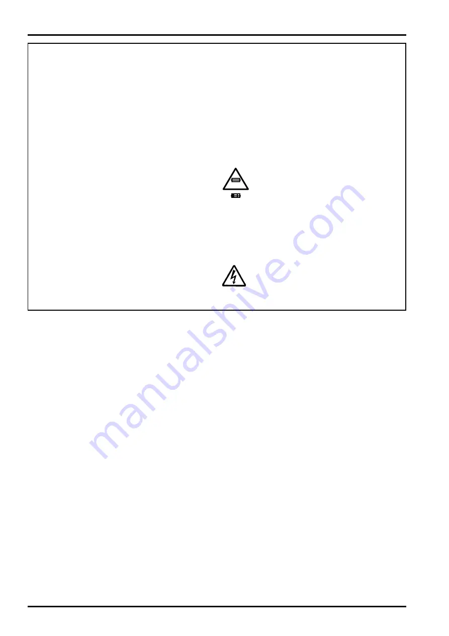
7.

CAUTION:

 FOR CONTINUED

PROTECTION AGAINST FIRE
HAZARD, REPLACE ONLY WITH
SAME TYPE 2.5 AMPERES 125V
FUSE.

ATTENTION:

 AFIN D'ASSURER

UNE PROTECTION PERMANENTE
CONTRE LES RISQUES
D'INCENDIE, REMPLACER
UNIQUEMENT PAR UN FUSIBLE
DE MEME, TYPE 2.5 AMPERES,
125 VOLTS.

8.

WARNING:

TO REDUCE THE ELECTRIC
SHOCK, BE CAREFUL TO TOUCH
THE PARTS.

WARNING!

  HIGH VOLTAGE

  SAFETY CHECK-OUT

After correcting the original problem, perform the following safety
check before return the product to the costomer.

2.5A125V

2.5A125V

RISK OF FIRE-
REPLACE FUSE
AS MARKED

Summary of Contents for FinePix6800Zoom

Page 1: ...E EG Model WARNING THE COMPONENTS INDENTIFIED BY THE MARK ON THE SCHEMATHIC DIAGRAM AND IN THE PARTS LIST ARE CRITICAL FOR SAFETY PREASE REPLACE ONLY BY THE COMPORNENTS SPECIFIED ON THE SCHEMATHIC DIAGRAM AND IN THE PARTS LIST IF YOU USE WITH PART NUMBER UN SPECIFIED IT MAY RESULT IN A FIRE AND AN ELECTORICAL SHOCK ...

Page 2: ...end their replacement 5 Check the B voltage to see it is at the values specified 6 Make leakage current measurements to deter mine that exposed parts are acceptably insulated from the supply circuit before returning the product to the customer 7 CAUTION FOR CONTINUED PROTECTION AGAINST FIRE HAZARD REPLACE ONLY WITH SAME TYPE 2 5 AMPERES 125V FUSE ATTENTION AFIN D ASSURER UNE PROTECTION PERMANENTE ...

Page 3: ...hematics 10 3 2 4 Process Block Schematics U_MODEL 11 3 2 5 Process Block Schematics E EG_MODEL 12 3 2 6 Audio Block Schematics 13 3 2 7 LCD Block Schematics 14 3 3 DC Board 3 3 1 DC Board Component Location 15 3 3 2 DC Block Schematics 16 3 4 CCD Board 3 4 1 CCD Board Component Location 17 3 4 2 CCD Block Schematics 18 3 5 ST Board 3 5 1 ST Board Component Location 19 3 5 2 Flash Block Schematics...

Page 4: ...ble resistors and semi variable resistor are abbreviated the specification of B characteristic 2 Basic Block 2 1 Overview of Functions of Each Circuit Board Name Circuit Diagram Name Circuit Functions MAIN Board CAM Block Schematic A D conversion of CCD output Signal circuit CCD Driver circuit Lens Shutter IRIS driving circuit PROCESS Block Schematic System control circuit Video Signal circuit Ima...

Page 5: ...fer of the SCS2D_IC and sent to the signal processor The 12 bit image data is converted to 8 bit Y and C signals in the signal processing unit and again sent to the on board buffer Each 8 bit Y and C signal is converted to 8 bit Y Y Cb and Cr signals which are then sent to the SDRAM_IC The image data stored in the SDRAM_IC is compressed in the JPEG processing unit in the SCS2D_IC and again saved i...

Page 6: ......

Page 7: ......

Page 8: ......

Page 9: ......

Page 10: ......

Page 11: ......

Page 12: ......

Page 13: ......

Page 14: ......

Page 15: ......

Page 16: ......

Page 17: ......

Page 18: ......

Page 19: ......

Page 20: ......

Page 21: ......

Page 22: ......

Page 23: ......

Page 24: ......

Page 25: ...26 30 Nishiazabu 2 chome Minato ku Tokyo 106 8620 Japan FUJI PHOTO FILM CO LTD ...

Reviews: