FRC-200S-1
Safety Information -
安全に関する情報
Protective equipment
Always wear necessary protective equipment such as
an eye protector, an ear protector, a face shield, a
safety apron, a helmet, gloves and other necessary
protective clothing. Use protective barriers where
necessary.
WARNING Risk of Property Damage or
Severe Injury
Ensure that you read, understand and follow all
instructions before operating the tool. Failure
to follow all the instructions may result in
electric shock, fire, property damage and/or
severe body injury.
►
Read all Safety Information delivered together
with the different parts of the system.
►
Read all Product Instructions for installation,
operation and maintenance of the different
parts of the system.
►
Read all locally legislated safety regulations
regarding the system and parts thereof.
►
Save all Safety Information and instructions
for future reference.
Statement of use
This product is designed for removing steel welding
beads.
No other use permitted. For professional use only.
Operation
See figures on page 2,3.
Fix the accessories properly to the tool.
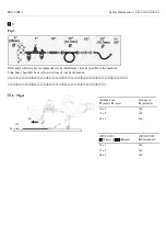
Use designated area for transportation to the
workpiece, see fig.2, to avoid unintentional start.
Connect device to a clean and dry air supply, with
suitable hose and connections according to fig.3.
To adjust cutter height,
o
turn the Lock Nut (D) counterclockwise
to unlock.
o
turn the Adjusting Handle (E) clockwise
to move the cutter up.
o
turn
the
Adjusting
Handle
(E)
counterclockwise to move the cutter
down.
o
adjust
the
cutting
depth
to
recommendation table fig.4.
o
turn the Lock Nut (D) clockwise to lock
cutter height.
To start operation,
o
Firmly hold the Main Handle (A) and the
Dead Handle (B).
o
Place the machine on the work piece at
up-right position as shown in fig.5. The
Cutter is not yet engaged with the
material at this stage, to prevent sudden
reaction.
o
Press the Trigger (C) and lower the Main
Handle slowly. When the Cutter contacts
the material, press the machine forward.
To stop operation,
o
Firmly hold the Main Handle (A) and the
Dead Handle (B).
o
Remove the tool from the workpiece
before stopping the cutter rotation., to
prevent sudden reaction.
o
Release the Trigger (C).
o
Visually confirm cutter stop before
putting the tool aside.
Caution for Safety Use of Air Supply
Air supply hose must be oil resistant and with
abrasion resistant exterior surface.
All connections must be in good condition and
properly installed. Do not use damaged, frayed
or deteriorated hose and fittings. Replace them
when necessary. Do not reform the hose and
fittings.
Always store the hose properly away from heat
sources and sunlight after use and inspect
before use. A hose failure can cause injury.
The use of a swivel coupling is recommended
so that rotating the tool will not distort or cause
disconnection of the supply hose.
Be sure to connect the hose to the machine
before switching on the air supply.
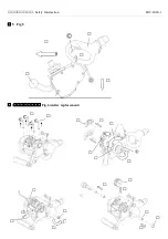
Cutter replacement
See Fig.6 page 3.
Disconnect air supply from the tool.
Make the machine face-up to see the cutter part.
Unfasten 4 pcs M6x25 Low head cap screw (A)
by an Allen head wrench (4mm Hex) .
Summary of Contents for FRC-200S-1
Page 4: ...Safety Information FRC 200S 1 5 Fig 5 6 Fig 6 cutter replacement...
Page 5: ......
Page 6: ...Safety Information FRC 200S 1 JA 6 EN Safety Information 10...
Page 9: ...FRC 200S 1 Safety Information...
Page 10: ...Safety Information FRC 200S 1 2 3 2 3 o D o E o E o 4 o D o A B o 5 o C o A B o o C o...
Page 12: ...Safety Information FRC 200S 1...

