background image

This  device  complies  with  part  15  of  the  FCC  Rules.  Operation  is  subject  to  the  following  two 

conditions: (1) This device may not cause harmful interference, and (2) this device must accept any 

interference received, including interference that may cause undesired operation. 

Note:  This  equipment  has  been  tested  and  found  to  comply  with  the  limits  for  a  Class  B  digital 

device,  pursuant  to  part  15  of  the  FCC  Rules.  These  limits  are  designed  to  provide  reasonable 

protection against harmful interference in a residential installation. This equipment generates, uses 

and  can  radiate  radio  frequency  energy  and,  if  not  installed  and  used  in  accordance  with  the 

instructions,  may  cause  harmful  interference  to  radio  communications.  However,  there  is  no 

guarantee that interference will not occur in a particular installation. If this equipment does cause 

harmful  interference  to  radio  or  television  reception,  which  can  be  determined  by  turning  the 

equipment off and on, the user is encouraged to try to correct the interference by one or more of the 

following measures: 


Reorient or relocate the receiving antenna. 


Increase the separation between the equipment and receiver. 


Connect  the  equipment  into  an  outlet  on  a  circuit  different  from  that  to  which  the  receiver  is 

connected. 


Consult the dealer or an experienced radio/TV technician for help. 

CAUTION  :  Changes  or  modifications  not  expressly  approved  by  the  party  responsible  for 

compliance could void the user’s authority to operate the equipment. 

FCC REGURATIONS 

In the European Union, Norway, Iceland and Liechtenstein:   

This symbol on the product, or in the manual, and/or on its packaging indicates 

that this product shall not be treated as household waste.    Instead it should be 

taken  to  an  applicable  collection  point  for  the  recycling  of  electrical  and 

electronic equipment. 

By  ensuring  this  product  is  disposed  of  correctly,  you  will  help  prevent  potential  negative 

consequences  to  the  environment  and  human  health,  which  could  otherwise  be  caused  by 

inappropriate waste handling of this product. 

Disposal of Electrical and Electronic Equipment in Private Households 

Canadian Radio Interference Regulation 

CAN ICES 3(B) / NMB-3(B) 

CAUTION : This Class B digital apparatus complies with Canadian ICES-003. 

Summary of Contents for FUJINON HA14x4.5 BEZD-T58B

Page 1: ...UA13x4 5BEZD T9 BB00041378 300 LP755A T9 2911...

Page 2: ......

Page 3: ...JAPANESE V English version Technical Drawings Technical Drawings ENGLISH...

Page 4: ......

Page 5: ......

Page 6: ......

Page 7: ...1 1 2 2 3 5 6 7 1 7 2 8 3 10 4 11 5 12 14 1 15 2 15 16 17 18 22 23 24 25 26 28...

Page 8: ...2 OFF a b c d e...

Page 9: ...1 2 3 m 3 6 7 a F f b c F f F f 3m d e f c g b f 2 3 b h F f 3 F f F f...

Page 10: ...4 F f F f c b g...

Page 11: ...5 A a M b 1 2 A M 19 ON...

Page 12: ...6 S...

Page 13: ...5 1 a OFF b 1 6 2 7 3 9 4 10 5 11 W T 7...

Page 14: ...2 a ON b T W HIGH LOW T W 7 8...

Page 15: ...ON OFF 20 ON OFF 9...

Page 16: ...3 a ON b c d 1 18 VTR 2 3 10...

Page 17: ...4 a ON b c d 18 VTR 3 1 2 3 11...

Page 18: ...5 ON OFF T W 12...

Page 19: ...ON OFF OFF ON 3 T 1 3 W 1 a b c d e OFF ON ON OFF OFF ON T W a b c OFF 1 2 3 4 1 2 ON OFF OFF OFF 13...

Page 20: ...2 1 14 2 14 14...

Page 21: ...1 ON OFF 18 ON ON 19 OFF OFF ON a b c a b 2 ON OFF 18 ON ON 19 ON ON S a b c a d b c M 15...

Page 22: ...a b c 16...

Page 23: ...2 VTR VTR VTR VTR 18 18 VTR 2 1 2 17...

Page 24: ...ON OFF ON OFF VTR VTR VTR ON OFF ON OFF ON OFF VTR ON OFF 18...

Page 25: ...ON OFF ON OFF OFF A M ON OFF ON OFF OFF ON A M ON OFF ON OFF 19...

Page 26: ...ON OFF ON OFF ON OFF ON OFF No 9 No 4 Normal No 0 W T 0 10 OFF ON OFF ON OFF ON OFF ON OFF ON OFF 20...

Page 27: ...SW1 SW1 ON RET OFF ON ON ON OFF SW1 SW1 ON OFF ON ON ON OFF SW1 SW1 ON ON ON OFF OFF ON OFF OFF ON SW1 A M A M OFF M A ON 21...

Page 28: ...22...

Page 29: ...a b a b c d 23...

Page 30: ...a b 1 1 24...

Page 31: ...2 5V 8 FOCUS POSITION Far 2 5V Near 7 5V 7 ZOOM CONTROL WIDE 7 5V TELE 2 5V 8 ZOOM POSITION WIDE 2 5V TELE 7 5V 9 9 VTR SW 10 N C 10 VTR SW COM 11 N C 11 RET SW 12 N C 12 RET SW COM HR25 9R 20S HIROS...

Page 32: ...1 1 EPD 4A E12A ERD 10A D01M EPD EBF 1 MCA 06BC ERD EPD 26...

Page 33: ...2 2 SA 206D 005 27...

Page 34: ...1 0 mm 16 9 in Air 48 mm 0 2 mm 0 3 m 0 04 m H V 93 6 61 8 9 3 5 2 56 1 33 3 4 7 2 6 744 mm 418 mm 54 mm 30 mm 367 mm 206 mm 28 mm 16 mm 86 3 mm 26 1 mm M127 0 75 at 12V DC 180 mA 900 mA 2 30 kg 2 0 6...

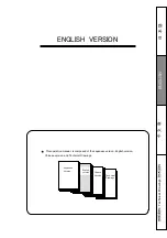
Page 35: ...ION This operation manual is composed of the Japanese version English version Chinese version and Technical Drawings Japanese Version English version Chinese Version Technical Drawings Technical Drawi...

Page 36: ...one or more of the following measures Reorient or relocate the receiving antenna Increase the separation between the equipment and receiver Connect the equipment into an outlet on a circuit different...

Page 37: ...rrying the lens Dropping the lens while carrying may cause injury Be sure to confirm that the camera to be used with the lens system lens and accessories is able to supply sufficient electric power to...

Page 38: ...mbient temperature of the place where the lens will be used Be sure not to apply impact to the front part of the lens when operating the camera Put the cap on the lens while the camera is not used If...

Page 39: ...Zoom Operation 11 5 Zoom Limit Operation 12 Preset Operation 14 1 Zoom Preset Operation 15 2 Zoom and Focus Simultaneous Preset Operation 15 Macro Operation 16 Other Functions 17 About Function Mode...

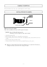
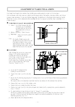
Page 40: ...face of the lens to that of the camera aligning the pin on the lens with the slot in the camera d Rotate the mount clamp ring fully clockwise Note Make sure to adjust the flange focal length when inst...

Page 41: ...bring the object into focus f Operate the zoom to set it to the wide end again and check that the optimum focus position adjusted in step c is kept g To adjust precisely repeat the above steps b thro...

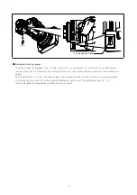
Page 42: ...gear located inside the cover using a finely pointed tool for example and adjust If this adjustment is to be performed replace the operation in step c above with the operation involved in rotating the...

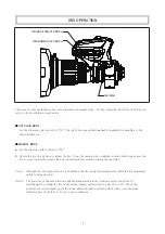
Page 43: ...es the iris to move toward the closed side and counterclockwise rotation toward the open side Note 1 Note 2 Although the iris operation mode is in Manual the iris is adjusted automatically while the i...

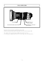
Page 44: ...e to focus on an object on the near side The remote control operation is also available with optional accessories Set the focus servo manual select knob to S when using a servo control accessory FOCUS...

Page 45: ...de and counterclockwise rotation to the tele side When rotating the zoom ring directly it is recommended to remove the zoom lever for smooth operation If you removed the zoom lever install it on the z...

Page 46: ...case the zoom may not reach the tele end or the wide end For servo operaion press the T side or the W side of the zoom seesaw control lever For manual operation rotate the zoom ring directly or using...

Page 47: ...be set to disabled when the zoom is controlled by a positional control method such as in a pan tilt head remote control system The setting can be done by means of the quickframe on off switch refer t...

Page 48: ...ng zoom switch Note 2 In quickzoom operation the zoom moves at the maximum speed irrespective of the setting position of the zoom maximum speed control knob Note 3 If you press the quickzoom auto crui...

Page 49: ...ee ways to release the auto cruising zoom operation mode 1 When the amount of displacement of the zoom seesaw control lever exceeds that determined when the auto cruising zoom operation is set the aut...

Page 50: ...de By using this function the zoom movement toward both the tele side and the wide side can be confined therefore zooming can be done within the desired shot angles 12 Note While the zoom limit functi...

Page 51: ...ition and stops Keep pressing the W side of the lever so that the zoom reaches the wide side zoom limit position and stops a b c With a digital zoom rate demand unit the zoom limit function of the zoo...

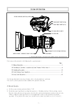
Page 52: ...ch mode Page PRESET OPERATION ZOOM SEESAW CONTROL LEVER PRESET SWITCH ON PRESET SWITCH MEMO CONNECTOR FOR ZOOM CONTROL FOCUS SERVO MANUAL SELECT KNOB QUICKFRAME MANUAL ZOOM SELECT KNOB While the zoom...

Page 53: ...a b c Storing Preset Position a Recalling Preset Shot The zoom and focus move to their predetermined positions then stop The zoom and focus start and stop simultaneously During this operation the shot...

Page 54: ...sition In this case the values of the M O D Minimum Object Distance and the object area at M O D are those of between a normal and a closeup shot PROCEDURE TO CANCEL Rotate the macro ring in the oppos...

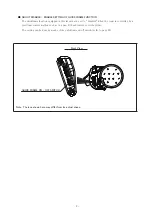
Page 55: ...8 Note Return Switch The return switch operates only when the camera supports the function of the switch Note Connector for Expansion While pressing this switch the return video picture can be seen th...

Page 56: ...hat of the quickzoom switch The function of the VTR switch incorporated in the zoom rate demand unit or the shot box linked to this lens is also changed to that of the quickzoom switch Return Qunckzoo...

Page 57: ...his switch Function Switch Using this switch the preset operation mode can be selected IRIS Compensation ON OFF Switch This switch changes the iris compensation function to ON and OFF Note In the iris...

Page 58: ...n failure FUNCTION MODE SELECT SWITCHES Rubber Cap AUXILIARY SWITCH ANALOG ZOOM DEMAND ZOOM MODE FUNCTION ON OFF SWITCH QUICKFRAME ON OFF SWITCH CAMERA COMMUNICATION ON OFF SWITCH ZOOM MODE SELECT SWI...

Page 59: ...nction of VTR Switch AutoCruisingZoom ON VTR QuickZoom OFF VTR Switch ON ON Quickzoom auto cruising zoom switch ON OFF Quickzoom switch QuickZoom Auto Cruising Zoom Switch Settings of Function Mode Se...

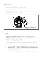
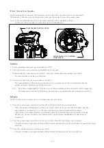
Page 60: ...recisely adjusted at the factory before shipment normally the readjustment is not required But when an abnormality occurs for some reason the readjustment can be made as described below The adjusting...

Page 61: ...the lens body contact with each other a Rotate the hood attaching knob counterclockwise to loosen it b Pull the lens hood straight toward the front to detach it c Rotate the lens hood so that the inde...

Page 62: ...ut it together with desiccant into a vinyl bag for sealing to remove the moisture inside STORAGE If it is assumed that the lens will not be used for a long term store it in a place where high temperat...

Page 63: ...0V DC 3 COM V 7 5V DC 5 COM V 2 5V DC 4 COM 5 0V DC FOCUS DEMAAND DETECT 5 COM V 2 5V DC 6 ZOOM DEMAND DETECT 6 7 FOCUS CONTROL Far 7 5V Near 2 5V 8 FOCUS POSITION Far 2 5V Near 7 5V 7 ZOOM CONTROL WI...

Page 64: ...n Demand Unit REMARKS MODEL OPTIONAL ACCESSORIES Note The speed of the zoom achieved by operating the ZOOM RATE DEMAND UNIT is the speed that reflects both the setting established for the zoom maximum...

Page 65: ...rol by Personal Computer Configuration All Servo System 2 ACCESSORY NAME EXTENSION CABLE SA 206D 005 Required when a personal computer is used to control the iris focus and zoom of the lens Lens Perso...

Page 66: ...Angle at Wide End at Tele End Object Area at M O D 744 mm 418 mm 54 mm 30 mm 367 mm 206 mm 28 mm 16 mm Front Rear Clear Aperture of Lens 86 3 mm 26 1 mm Filter Screw M127 0 75 Iris Control Servo or Ma...

Page 67: ...Technical Drawings ENGLISH English version...

Page 68: ...SJ T11364 GB T26572 GB T26572 10...

Page 69: ......

Page 70: ......

Page 71: ...1 1 2 2 3 5 6 7 1 7 2 8 3 10 4 11 5 12 14 1 15 2 15 16 17 18 22 23 24 25 26 28...

Page 72: ...2 a b c d e...

Page 73: ...3 1 2 3 3 6 7 a b c 3 d e f c g b f b h...

Page 74: ...4 c b g...

Page 75: ...5 A a M b 1 2 A M 19...

Page 76: ...6 S...

Page 77: ...7 1 a OFF b 1 7 2 8 3 10 4 11 5 12 T W...

Page 78: ...8 2 a ON b T W HIGH LOW T W 7...

Page 79: ...9 ON OFF ON OFF OFF 20 ON OFF...

Page 80: ...3 a ON b c d 1 18 VTR 2 3 10...

Page 81: ...4 a ON b c d 18 VTR 1 2 3 11...

Page 82: ...5 12 ON OFF T W...

Page 83: ...13 ON OFF OFF 1 2 3 4 1 2 OFF ON ON OFF OFF ON T W a b c ON OFF OFF ON 3 T 1 3 W 1 a b c d e...

Page 84: ...14 1 15 2 15 ON MEMO...

Page 85: ...1 15 ON OFF 18 ON ON 19 OFF OFF ON a b c ON a b ON 2 ON OFF 18 ON ON 19 OFF ON S a b c a ON EPD 4A E01 EPD 4A E02 d b c ON...

Page 86: ...16 a b c M O D ON OFF OFF 12...

Page 87: ...17 2 2 2 VTR VTR VTR VTR VTR 18 18 VTR 2 1 2...

Page 88: ...18 ON OFF ON OFF OFF VTR VTR VTR ON OFF ON OFF ON OFF VTR ON OFF...

Page 89: ...19 ON OFF ON OFF OFF A M ON OFF ON OFF OFF ON A M ON OFF ON OFF...

Page 90: ...ON OFF ON OFF ON OFF ON OFF 10 OFF ON OFF ON OFF ON OFF ON OFF ON OFF No 9 No 4 No 0 W T 0 20...

Page 91: ...21 VTR SW1 SW1 RET OFF ON ON ON OFF SW1 SW1 OFF ON ON ON OFF SW1 SW1 ON ON OFF OFF ON OFF OFF ON SW1 A M A M OFF M A ON...

Page 92: ...22...

Page 93: ...23 a b a b c d...

Page 94: ...24 a b...

Page 95: ...2 5V 8 FOCUS POSITION Far 2 5V Near 7 5V 7 ZOOM CONTROL WIDE 7 5V TELE 2 5V 8 ZOOM POSITION WIDE 2 5V TELE 7 5V 9 9 VTR SW 10 N C 10 VTR SW COM 11 N C 11 RET SW 12 N C 12 RET SW COM HR25 9R 20S HIROS...

Page 96: ...26 1 1 EPD 4A E12A ERD 10A D01M EPD EBF 1 EPD ERD MCA 06BC...

Page 97: ...27 2 2 SA 206D 005...

Page 98: ...9 mm F3 6 F5 2 F1 8 F16 9 59 5 39 mm 11 0 mm 16 9 48 mm 0 2 mm 0 3 m 0 04 m 744 mm 418 mm 54 mm 30 mm 367 mm 206 mm 28 mm 16 mm 86 3 mm 26 1 mm M127 0 75 B at 12V DC 2 93 6 61 8 9 3 5 2 56 1 33 3 4 7...

Page 99: ...TECHNICAL DRAWINGS Technical Drawings ENGLISH...

Page 100: ...R VTR SWITCH VTR EXTENDER SELECT LEVER INDEX MARK INDEX LINE IRIS RING 2 THREADED HOLE FOR ZOOM SERVO MODULE 2 PLACES 2 PRESET SWITCH ZOOM LIMIT SWITCH IRIS SENSITIVITY ADJUSTING TRIMMER FUNCTION MODE...

Page 101: ...SS00002038 00 mm UNLESS OTHERWISE SPECIFIED UNIT mm Outline drawing UA13 X 4 5BEZD T9 Fig 1 1...

Page 102: ......

Page 103: ...MEMO...

Page 104: ...MEMO...

Page 105: ...SIEMENS STAR...

Page 106: ......

Page 107: ......

Page 108: ......

Reviews: