5
PARAMETERS
5-52
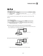
Control system setting parameters #57 through #60
No.
Name
Setting range
Initial value
Change
57
Notch filter 1 frequency
10 to 200 [x 100 Hz] (in 1 increments)
200
Always
58
Notch filter 1 damping amount
0 to 40 [dB] (in 1 increments)
0
Always
59
Notch filter 2 frequency
10 to 200 [x 10Hz] (in 1 increments)
200
Always
60
Notch filter 2 damping amount
0 to 40 [dB] (in 1 increments)
0
Always
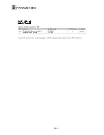
Specify to suppress resonance of the mechanical system.
Resonance can be suppressed at up to two points.
n
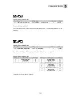
Notch filter setting method
i) Use the servo analysis function of the PC loader (option) to determine the resonance point
of the machine.
ii) Specify the resonance frequency and damping amount of the resonance point of the
machine in parameters.
1 Resonance frequency
→
Parameter #57 (Notch filter 1 frequency)
2 Depth
→
Parameter #58 (Notch filter 1 damping amount)*
* Too deep a damping amount may undermine stability of the control. Avoid setting too large a value.
Notch filter 1,
damping amount
Notch filter 1,
frequency
Use the servo analysis
function again.
The notch filter functions at the resonance
point as shown in the figure above.
The resonance point is eliminated
due to the notch filter.
Gain
[dB]
Frequency [Hz]
Resonance point
1 Resonance frequency
2 Depth
Summary of Contents for GYN101CAG-G09
Page 1: ...FUJI AC SERVO SYSTEM USER S MANUAL MEH395 ...
Page 2: ......
Page 10: ......
Page 20: ...1 Outline 1 10 MEMO ...
Page 21: ...2 1 Servomotor 2 2 Servo amplifier INSTALLATION ...
Page 32: ...2 INSTALLATION 2 12 MEMO ...
Page 46: ...3 WIRING 3 14 MEMO ...
Page 52: ...3 WIRING 3 20 MEMO ...
Page 64: ...3 WIRING 3 32 MEMO ...
Page 65: ...4 1 Test operation in two stages 4 2 First stage 4 3 Second stage TEST OPERATION ...
Page 70: ...4 TEST OPERATION 4 6 MEMO ...
Page 85: ...PARAMETERS 5 5 15 MEMO ...
Page 132: ...6 ADJUSTMENT OF SERVO 6 8 MEMO ...
Page 164: ...8 KEYPAD PANEL 8 18 MEMO ...
Page 186: ...9 INSPECTION AND MAINTENANCE 9 22 MEMO ...
Page 226: ...11SPECIFICATIONS 11 14 MEMO ...
Page 234: ...11SPECIFICATIONS 11 22 Servo amplifier Unit mm Unit mm Unit mm ...
Page 235: ...APPENDIXES Inertia moment calculation Load torque Timing chart ...
Page 250: ...APPENDIXES Appendix 16 MEMO ...
Page 251: ...APPENDIXES Appendix 17 MEMO ...


