3
WIRING
3-28
n
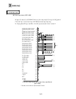
Positioning unit (AD75 type)
Example of connection with AD75 type positioning unit made by Mitsubishi Electric Co., Ltd.
Only connections between the AD75 positioning unit and servo amplifier are shown.
For the programmable logic controller, refer to the operation manual or user’s manual of the
equipment.
The connection diagram shown in this chapter is only for reference.
Controller side
3
PULSE F+
21
PULSE F-
4
PULSE R+
22
PULSE R-
24
PGO(5V)
25
PGO COM
26
COM
9
PULSER A+
27
PULSER A-
10
PULSER B+
28
PULSER B-
11
DOG
12
FLS
13
RLS
14
STOP
15
CHG
16
STAT
35
COM
36
COM
①
②
③
④
7
READY
8
INPS
⑤
⑥
⑦
⑧
P24
M24
⑨
⑩
Ground the shielding
wire at both ends.
Positioning unit
(
AD75P1-S3
)
Summary of Contents for GYN101CAG-G09
Page 1: ...FUJI AC SERVO SYSTEM USER S MANUAL MEH395 ...
Page 2: ......
Page 10: ......
Page 20: ...1 Outline 1 10 MEMO ...
Page 21: ...2 1 Servomotor 2 2 Servo amplifier INSTALLATION ...
Page 32: ...2 INSTALLATION 2 12 MEMO ...
Page 46: ...3 WIRING 3 14 MEMO ...
Page 52: ...3 WIRING 3 20 MEMO ...
Page 64: ...3 WIRING 3 32 MEMO ...
Page 65: ...4 1 Test operation in two stages 4 2 First stage 4 3 Second stage TEST OPERATION ...
Page 70: ...4 TEST OPERATION 4 6 MEMO ...
Page 85: ...PARAMETERS 5 5 15 MEMO ...
Page 132: ...6 ADJUSTMENT OF SERVO 6 8 MEMO ...
Page 164: ...8 KEYPAD PANEL 8 18 MEMO ...
Page 186: ...9 INSPECTION AND MAINTENANCE 9 22 MEMO ...
Page 226: ...11SPECIFICATIONS 11 14 MEMO ...
Page 234: ...11SPECIFICATIONS 11 22 Servo amplifier Unit mm Unit mm Unit mm ...
Page 235: ...APPENDIXES Inertia moment calculation Load torque Timing chart ...
Page 250: ...APPENDIXES Appendix 16 MEMO ...
Page 251: ...APPENDIXES Appendix 17 MEMO ...


