


41S_Rev00
24
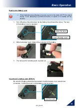
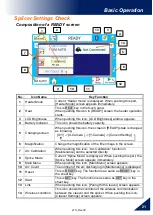
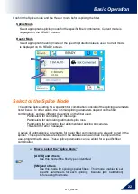
Basic Operation
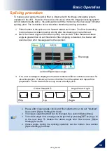
Select of the Heater Mode
Each tube-heating mode is optimized for a type of Fujikura protection sleeve. These modes
can be found in database area for reference. Copy the appropriate one and paste it to the
user-programmable area. The operator can edit the user-programmable modes.
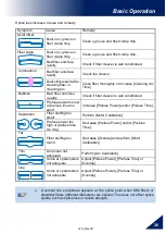
Data Base
Parameter
Description
60mmS
FP-03
For standard 60mm protection sleeve,
Such as Fujikura FP-03 or FP-03M protection sleeves.
60mmS
FP-03(250um)
For standard 60mm protection sleeve and 250um diameter coating,
Such as Fujikura FP-03 or FP-03M protection sleeves.
40mmS
FP-03(L=40)
For standard 60mm protection sleeve,
Such as Fujikura FP-03 or FP-03M protection sleeves.
Note : Cleave length 8mm.
60mmSS
SLIM 60
For slim type 60mm protection sleeve.
40mmSS
SLIM 40
For slim type 40mm protection sleeve.
15mmS
FPS01-400-15
For 400 or less um diameter coating and splice length of 5 mm or less
20mmS
FPS01-900-20
For 900 or less um diameter coating and splice length of 6 mm or less
60mmS
FPS01-DC-60
For drop cable splice.
FUSE900
SC-LC-ST-FC
For Fuse connect splice.
FUSE2/3
SC-LC
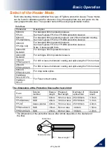
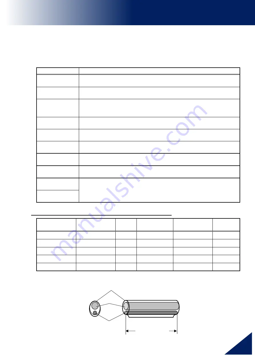
The dimensions of the Protection Sleeve after heat shrink
Form
Tension
member
Sleeve
length
Prepared
fiber length
Diameter of
optical fiber
Diameter
result
FP-03
SUS
60mm 16mm or less 250~900um
3.1mm
FP-03(40mm)
SUS
40mm
10mm or less
250~900um
3.1mm
FP-04T
Glass ceramic 40mm
10mm or less
250~900um
4.0mm
FPS01-400-15 SUS
15mm 5mm or less
~400um
1.5mm
FPS01-900-20 SUS
20mm 6mm or less
~900um
2.3mm
* The dimensions of the protection sleeve after shrink depends on the diameter of
the fiber.
Sleeve length *
Outer tube
Inner tube
Tension member


