41S_Rev00
57
Splice Menu
Detail of the parameters in splice mode
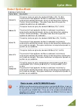
AUTO mode: [SM AUTO] ], [MM AUTO] ], [NZ AUTO] ], [DS AUTO] [AUTO SM/NZ/DS]
Below is a list of Splicing parameters for AUTO modes
Only a limited number of parameters listed below are displayed for AUTO modes to
simplify the operation. Additional hidden parameters are all fixed values set at the factory.
Parameter
Description
Fundamental Settings
Fiber Type
List of splice modes stored in database is displayed. A selected splice mode
stored in the database area is copied to a selected splice mode in the
user-programmable area.
Mode Title1
Title for a splice mode expressed in up to 11 characters.
Mode Title2
Detail explanation for a splice mode expressed in up to 15 characters. Title2
is displayed at the [Splice Mode Select] menu.
Rearc Time
Splice loss may be improved by an additional “rearc” discharge in some
cases. The duration of this additional arc can be changed by this parameter.
Proof Test
If [Proof Test] is set to "ON", a proof-test is performed upon opening the wind
protector after splicing or by pressing the RESET key.
Arc
Cleaning Arc
A cleaning arc burns out micro dust on the surface of the fiber with an arc
discharge for a short period of time. The duration of the cleaning arc can be
changed by this parameter.
Arc Power
The Arc Power is fixed at STANDARD for AUTO modes.
The Arc Power is changed automatically.
Arc Time
Arc Time is fixed at 6000ms. This is automatically set depending on the
cladding illumination during Arc Discharge.
Estimation
Estimating
Mode
Selects splice loss estimation to "OFF", ”Clad”, “WSI” or “Clad+WSI”.
OFF: Not display the estimation loss after splicing
Clad: Display the loss calculated from the cladding image.
WSI: Display the loss calculated from the fiber image during the arc
discharging. *Warm Splice Image
Clad+WSI: Display the loss of Clad and WSI.
Note: Generally, the estimation loss of WSI is higher than the
estimation loss of Clad.
MFD
Sets MFD of the fibers. This MFD value is taken into account for estimating
splice loss.
Minimum
Loss
This amount is added to the estimated splice loss originally calculated.
When splicing specialty or dissimilar fibers, a high actual splice loss may
occur even with optimized arc conditions. To make the actual splice loss
concur with the estimated splice loss, set the minimum value of estimate to
the minimum optimized actual splice loss.
Error Limit
Cleave Angle
Limit
An error message is displayed if the cleave angle of either the left or right
fiber ends exceeds the selected threshold (cleave limit).
Cleave Shape
Error
Error message is displayed if the cleaved end face of either left or right fiber
exceeds the selected threshold (cleave shape).
Fiber Angle
Limit
An error message is displayed if the fiber offset exceeds the selected
threshold (Fiber Angle).
Loss Limit
An error message is displayed if the estimated splice loss exceeds selected
threshold (loss limit).

