background image

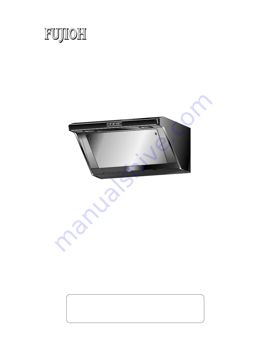
Range Hood

INSTALLATION MANUAL

MODEL: FDR-4200

FDR-4200D

1U030481

READ AND SAVE THESE INSTRUCTIONS.

Keep this manual in a convenient place for future reference.

FUJI INDUSTRIAL CO., LTD.

TABLE OF CONTENTS

Safety Instructions .............................................................................................. 2
Name of Parts ..................................................................................................... 4
Size & Dimensions .............................................................................................. 5
Range Hood Location ......................................................................................... 5
Installation ........................................................................................................... 6

1. Preparation ................................................................................................ 6
2. Range Hood Mounting ............................................................................... 9
3. Connecting Power Supply Wires ............................................................. 10
4. Attaching Duct Cover ............................................................................... 11
5. Final Assembly and Check ...................................................................... 12

Explanation to the End User ............................................................................. 13
Circuit Diagram ................................................................................................. 13

Summary of Contents for FDR-4200

Page 1: ...e for future reference FUJI INDUSTRIAL CO LTD TABLE OF CONTENTS Safety Instructions 2 Name of Parts 4 Size Dimensions 5 Range Hood Location 5 Installation 6 1 Preparation 6 2 Range Hood Mounting 9 3 Connecting Power Supply Wires 10 4 Attaching Duct Cover 11 5 Final Assembly and Check 12 Explanation to the End User 13 Circuit Diagram 13 ...

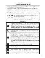
Page 2: ...hen the service disconnecting means cannot be locked securely fasten a prominent warning device such as a tag to the service panel 2 To reduce the risk of fire or electric shock do not use this range hood with any solid state speed control device 3 TO REDUCE THE RISK OF FIRE ELECTRIC SHOCK OR INJURY TO PERSONS OBSERVE THE FOLLOWING a Installation work and electrical wiring must be done by a qualif...

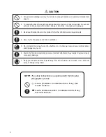
Page 3: ...ly for the purpose of kitchen ventilation 5 Do not install this range hood in the bathroom or in other wet rooms since electrical shock and damage may result 1 For general ventilating use only Do not use to exhaust hazardous or explosive material and vapors 7 Keep your hands and other objects away from the fan while it is in motion If not personal injury or damage may result means prohibition It i...

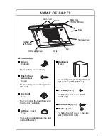
Page 4: ...the hood body to the side wall For connecting the hood body with the duct for ventilation Soft tape black 1 pc For sealing a gap between the duct joint and the duct For fixing the duct cover FDR 4200D only FT screw 4 pcs For covering and protecting the duct joint portion FDR 4200D only Wood screw 2 pcs Washer 2 pcs For fixing the duct cover to the side wall FDR 4200D only Oil Receiving Cover Spice...

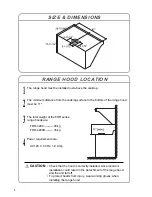
Page 5: ...e FDR series range hoods are FDR 4200 28 kg FDR 4200D 35 kg 4 Power requirements are AC120 V 60 Hz 1 9 Amp RANGE HOOD LOCATION CAUTION Check that the hood is correctly installed since incorrect installation could result in the detachment of the range hood and the unit fall off To protect hands from injury wear working gloves when installing the range hood SIZE DIMENSIONS 5 ...

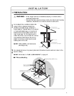
Page 6: ...ransitions and elbows Be sure to attach a roof cap or wall cap to avoid leaking rain in the end NOTE FDR 4200D is for horizontal discharge only 2 Use diagrams below for proper placement of ductwork and electrical cutout in the wall or ceiling NOTE Refer also to SIZE DIMENSIONS on page 5 INSTALLATION WARNING If the range hood is not installed properly it could become detached and fall off Ensure th...

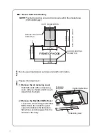
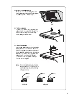
Page 7: ...3 Run house wiring between service panel and hood location 4 Prepare the range hood 1 Remove the oil receiving cover Hold both ends of the oil receiving cover with your hands and lift it up to detach from the body 2 Remove the Rectifier Baffle Panel Loosen the screws fixing the Rectifier Baffle Panel then slide the panel upward to dislocate the temporary fixing holes and disengage from the catches...

Page 8: ...y using these screws 5 Fix the duct joint Insert one bottom end of the supplied duct joint into the holder on the rear top of the body and fix the duct joint firmly using 2 screws on its front side The fixing screws are supplied with attaching to the top of the body Then attach the supplied soft tape around the duct joint Note When mounting the duct joint pay attention to the direction of its shut...

Page 9: ...e temporary fixing holes of the hangers on the screws slide the body downward then tighten the screws 3 Insert 2 more washer head wood screws in the holes of the body and tighten them firmly 4 Connect duct and duct joint then make the duct joint secure and air tight using non flammable tape such as duct tape etc not supplied Duct Tape etc Duct CAUTION The range hood is quite heavy FDR 4200D 35kg F...

Page 10: ...ower wiring WARNING Be sure to switch power OFF at service panel before wiring 2 Remove 1 screw fixing the wire box cover and detach the cover 3 Connect the conduit through the connecting hole of the body using the nut previously removed 4 Connect the electrical wires as follows Connect wires tightly and securely using wire connectors not supplied Black to Black White to White Green to Green 5 Mak...

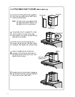
Page 11: ...top plate and screwheads 3 Put the duct cover with aligning its 4 bottom cutouts with the 4 screws slide it backward then tighten the screws firmly 4 Insert 2 supplied wood screws with washers in the holes left and right on the back bracket of the duct cover and tighten them securely 5 Replace the front panel with engaging its top notches first then pushing its bottom side to set into the roller c...

Page 12: ...the slot filters with 2 screws 3 Replace the Rectifier Baffle Panel with 2 screws 4 Replace the oil receiving cover 2 Check 1 Turn on the electrical circuit to the range hood 2 Make sure that the switch and light operate correctly Refer to page 5 of the Operation Manual 3 Check the ventilating functions at Hi Me and Lo positions 4 Make sure that the range hood has no abnormal noises and or vibrati...

Page 13: ...Brown Blue Red Orange Brown Blue Orange Brown Blue Capacitor 8µF 440VAC Gray Gray Gray Red White Model No 1U204261 Capacitor Running Induction Motor Single phase 120V 60Hz 220W Ins Class A 4 Poles Auxiliary Coil 2 Auxiliary Coil 3 Thermal Cutoffs Thermal Cutoffs Auxiliary Coil Main Coil 1 E76560 Explanation to the End User 1 Referring to the Operation Manual explain the operation of this range hoo...

Page 14: ...Fuji Industrial Co Ltd 2 1 9 Fuchinobe Sagamihara shi Kanagawa ken 229 0006 Japan Tel 81 42 753 1001 Fax 81 42 753 1009 1U030481 ...

Reviews: