Color monitor 21P3
8 - English
A26361-K618-Z100-2-5E19
2
1
3
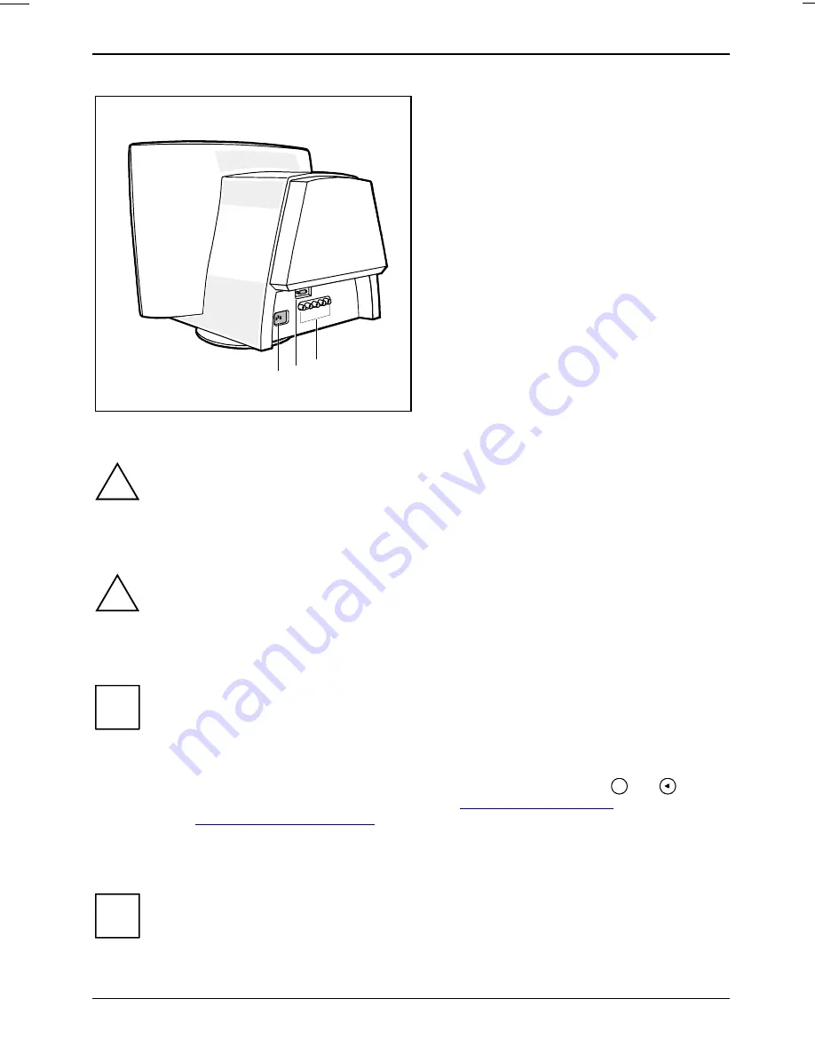
1 = Power connector
2 = D-SUB connector (INPUT A)
3 = BNC connectors (INPUT B)
Ê
Be sure that the monitor and the system unit are switched off.
!
The system unit's power plug must be pulled out!
The data cable supplied has two 15-pin D-SUB connectors for connection to the monitor and to the
system unit.
!
CE conformance and optimum picture quality are guaranteed only if you use the data
cable supplied.
Ê
Connect one of the connectors of the data cable to the D-SUB connector on the monitor (2)
and secure the plug-in connection by tightening the safety screws.
i
If you use a data cable with BNC connectors instead of the supplied data cable, you
should perform the following step:
Ê
Connect the BNC connectors of the data cable to the appropriate BNC connectors
on the monitor (3), correct order from left to right: Red-Green-Blue-H-V, and secure
the plug-in connections by locking the bayonet catches.
Ê
Change the video signal in the OSD menu or by pressing the keys
OK
and
(INPUT A/B) simultaneously (see chapter "
Operation of the monitor
", section
"
Settings with the OSD menu
").
Ê
Connect the other connector of the data cable to the (active) monitor port on the system unit
and secure the plug-in connection by tightening the safety screws.
i
If your system unit has two monitor ports ("onboard" screen controller and separate
graphics card), the monitor port for the separate graphics card is usually active.

