background image

Colour monitor B15-1

2  - English

A26361-K905-Z100-2-5E19

Notational conventions

The meanings of the symbols and fonts used in this manual are as follows:

!

Pay particular attention to text marked with this symbol. Failure to observe this warning
endangers your life, destroys the device, or may lead to loss of data.

i

Supplementary information, remarks, and tips follow this symbol.

Ê


Text which follows this symbol describes activities that must be performed in the order shown.

"Quotation marks" indicate names of chapters or terms.


Texts in italics

 indicate filenames and menu items.

Important notes

!

In this chapter you will find information regarding safety which is essential to take note of
with your monitor.

Safety notes

This device complies with the relevant safety regulations for data processing equipment, including
electronic office machines for use in an office environment. If you have any questions, contact your
sales outlet or our help desk.


The display surface of the LCD monitor is sensitive to pressure and scratches. You should
therefore be careful with the display surface so as to avoid lasting damage (Newton rings,
scratches).


If the device is brought into the installation site from a cold environment, condensation can
form. Before operating the device, wait until it is absolutely dry and has reached approximately
the same temperature as the installation site.


During installation and before operating the device, please observe the instructions on
environmental conditions in the "Technical data" chapter as well as the instructions in the
"Installing an ergonomic video workstation" chapter.


To ensure sufficient ventilation, the intake and exhaust air openings of the monitor must never
be blocked.


The device automatically sets itself to the correct voltage within the range from 100 V to 240 V.
Ensure that the local mains voltage lies within these limits.


Ensure that the power socket on the device or the grounded mains outlet is freely accessible.


The ON/OFF switch does not disconnect the device from the mains voltage. To completely
disconnect the mains voltage, remove the power plug from the socket.


Lay all cables so that nobody can stand on them or trip over them. When attaching the device,
observe the relevant notes in the "Connecting the monitor" chapter.

Summary of Contents for B15-1

Page 1: ...t 6 Installing an ergonomic video workstation 6 Connecting the monitor 7 Connecting cables to the monitor 8 Connecting cables to the computer 9 Operation of the monitor 9 Adjusting rake and rotation 9...

Page 2: ......

Page 3: ...arm and wall bracket plug play capability power management for reducing power consumption when the computer is not in use compliance with the recommendations in accordance with TCO 03 In normal screen...

Page 4: ...therefore be careful with the display surface so as to avoid lasting damage Newton rings scratches If the device is brought into the installation site from a cold environment condensation can form Bef...

Page 5: ...t only those resolutions and refresh rates specified in the Technical data chapter Otherwise you may damage your monitor If you are in any doubt contact your sales outlet or our help desk Keep this op...

Page 6: ...all savings in electricity could amount to 2 thousand million annually These savings could also prevent the emission of 20 million tons of carbon dioxide into the atmosphere the equivalent of 5 millio...

Page 7: ...o do so may violate FCC rules Disposal and recycling This device has been manufactured to the highest possible degree from materials which can be recycled or disposed of in a manner that is not enviro...

Page 8: ...erating manual Should you discover that the delivery does not correspond to the delivery note notify your local sales outlet immediately i It is recommended not to throw away the original packaging ma...

Page 9: ...e use of a swivel arm or wall bracket VESA FPMPMI are available from specialised dealers may be advisable For this purpose the monitor base must be removed beforehand as described in Removing the moni...

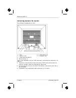
Page 10: ...data cable supplied has two 15 pin D SUB connectors for connection to the monitor and to the system unit Connect one of the connectors of the data cable to the D SUB connector on the monitor 3 and se...

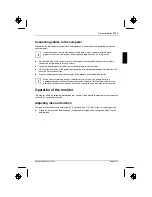
Page 11: ...pplied into a properly grounded mains outlet and ensure a secure connection Plug the power connector of the computer into a properly grounded mains outlet i When you start working with your monitor fo...

Page 12: ...ur computer has a power management function energy saving mode you should read the Notes on power management section in this chapter Notes on power management If your computer is equipped with power m...

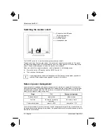
Page 13: ...the operating systems Windows 95 98 Windows NT Windows Me Windows 2000 Windows XP or OS 2 with Windows emulation installed is used the basic monitor settings can be set with the floppy disk supplied...

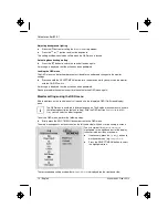
Page 14: ...o release the locked OSD menu again Monitor settings using the OSD menu With the buttons on the control panel call up and use the integrated OSD On Screen display menu i The OSD menu is available in d...

Page 15: ...the following Adjusting the brightness and contrast Calling the Brightness Contrast setting window Brightness Setting the brightness of the display With this function you change the brightness of the...

Page 16: ...perature The warmth of the screen colours is set using the colour temperature The colour temperature is measured in K Kelvin You can select from 6500 K 9300 K Native and Custom Colour Native Custom Co...

Page 17: ...d On a message appears on the screen after approx 30 seconds if a different resolution is set Change the resolution to 1024 x 768 to achieve optimum picture quality With the function deactivated Off n...

Page 18: ...ble for continuous text and data entry When using several colours for characters and background and giving the primary colours full modulation you can obtain very suitable colour combinations see the...

Page 19: ...h off the monitor and pull the power plug out of the power socket Lay the monitor on its face on a soft surface Remove the cover and disconnect all cables Remove the screw on the rear of the monitor Y...

Page 20: ...wer cable 1 8 m D SUB data cable 1 8 m Storable display modes 22 Electrical data Video analogue positive 0 7 Vpp 75 Synchronisation Separate Sync TTL positive or negative Horizontal frequency 30 kHz 6...

Page 21: ...Nixdorf MCF 3511 TA MCM 1405 ND Preset operating modes i The picture position and size have been set to optimum values at the factory for the operating modes listed above Depending on the screen cont...

Page 22: ...able to solve the problem please inform our help desk Having this problem Check the following points No display power indicator does not light Check whether the monitor is switched on Check whether th...

Page 23: ...o perform the auto adjustment of the screen Set the picture position with the OSD menu see Operation of the monitor Having this problem Check the following points Picture is shaking Check whether the...

Page 24: ...er of pixels faults is stipulated in the stringent international standard ISO 13406 2 Class II Example a 15 flat screen monitor with a resolution of 1024 x 768 has 1024 x 768 786432 pixels Each pixel...

Reviews: