FSC B15-1A Service Manual
11
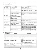
4.3 Power Supply Requirements
4.3.1 Input Requirements
PARAMETER RANGE
CONDITION
Input Voltage
90 to 264VAC RMS
Universal input full range
Input Frequency
47 Hz to 63 Hz
110V AC 60Hz; 220V AC 50 Hz
Less than 2.0 Amps RMS
Input voltage 100 VAC RMS ; 60 Hertz.
Parameter must be reached within 3 seconds of
turn-on.
Input Current
Less than 1.0 Amps RMS
Input voltage 220 VAC RMS ; 50 Hertz.
Parameter must be reached within 3 seconds of
turn-on.
Input Power
Less than 75 Watts
Power factor > 0.5 Input voltage 120 VAC RMS ; 60
Hertz
Less than 30 A peak
Input voltage 100 VAC RMS ; 60 Hertz at all
Phase(0, 90, 180, 270 degree)
Inrush Current
Less than 50 A peak
Input voltage 240 VAC RMS ; 50 Hertz at all
Phase(0, 90, 180, 270 degree)
Input Fusing
Fuse should be located internal to
the adapter, easily accessible
when the cover is removed
Fuse must be UL/CSA approved. Fuse value
must no have to change for 115 VAC or 230 VAC
operation
Leakage Current
Less than 3.5 mA
Input voltage 240 Volts RMS ; 50 Hertz
Primary to secondary
1.5KVAC for 1 Minute(leakage current 10mA)
1.8KVAC for 1 Minute(leakage current 10mA)
3.0KVAC for 1 Minute(leakage current 10mA)
without Y-cap & Coupling cap.
Hi-Pot
Primary to Saft Ground
1.5KVAC for 1 Minute(leakage current 10mA)
1.8KVAC for 1 Minute(leakage current 10mA)
4.3.2 Output Requirements
PARAMETER RANGE
CONDITION
DC Out
12VDC ± 5%
Min 0A Max 3.75A
Load Regulation 12.0V(12.12V) ± 5%
11.4 to 12.6VDC
Dynamic Load
Regulation
Any frequency up to 250Hz(duty
50%)
±
5% for 10% to 100%, 100% to 10% load
change for
+12Vdc
Ripple & noise
170mVpp at 12VDC
Input voltage : 100VAC at 60Hz 240VAC at
50Hz
* Ripple and noise are measured.
Output current
protection
less than 7.0A, more than 12.0A
at 12.0VDC
Current exceeds maximum rateing more than
20%
Leakage Current Less than 0.25 mA
Input voltage 100 Volts RMS ; 50 Hertz
Less than 0.5 mA
Input voltage 240 Volts RMS ; 50 Hertz
Summary of Contents for FSC B15-1A
Page 14: ...FSC B15 1A Service Manual 14...
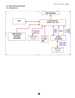
Page 17: ...FSC B15 1A Service Manual 17 5 3 Electrical Block Diagram 5 3 1 Main Board...
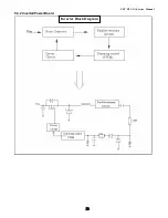
Page 18: ...FSC B15 1A Service Manual 18 5 3 2 Inverter Power Board Inverter Block Diagram...
Page 19: ...FSC B15 1A Service Manual 19 Power Block Diagram...
Page 25: ...FSC B15 1A Service Manual 25 7 PCB Layout 7 1 Main Board 715L1225 C...
Page 26: ...FSC B15 1A Service Manual 26...
Page 27: ...FSC B15 1A Service Manual 27 7 2 Inverter Power Board 715L1063 1A...

