background image


FSC B15-1A Service Manual 

21 

C301

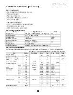
NC

C312

220pF

C315

0.1uF NC

D309

BAV99 NC

3

1

2

C304 0.047uF

R314

10K  1/16W


D320
MLL5232B 5.6V

VSYNC

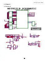
4

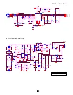
DVI5V

R311

1K  1/16W


D304

BAT54C-GS08

3

1

2

G+

4

R320

100  1/16W NC


CLK_DDC2

D310

BAV99 NC

3

1

2

VCC5V

DAT_DDC

D306

BAV99 NC

3

1

2

R+

4

R326

75

 1/16W


C310 0.047uF

R321

10K  1/16W NC


BIN

4

FB303

0  1/16W


C309 0.047uF

D301

BAV99

3

1

2

R322

100  1/16W NC


C313

0.1uF

D312

BAV99 NC

3

1

2

CLK+

4

DVI5V

C314

0.1uF NC

HSI

C308 0.047uF

D317
MLL5232B 5.6V

R324

20K  1/16W NC


GIN

4

ST_DET2 6

PC5V

VSI

CLK-

4

D307

BAV99 NC

3

1

2

VCC5V

R317

20K  1/16W


D308

BAV99 NC

3

1

2

D318
MLL5232B 5.6V

CLK_DDC

U302

AT24C02N-10SC NC

1
2

3

4

5

6

7

8

A0

A1

A2

GND

SDA

SCL

WP

VCC

D303

BAV99

3

1

2

B+

4

R313

2.2K  1/16W


R307

100  1/16W


D319
MLL5232B 5.6V

R310

150  1/16W


D302

BAV99

3

1

2

DAT_DDC2

RIN

4

SOG

4

VCC5V

CN301

DB15

1
6

2
7

3

8
4

9

5

11

12

13

14

15

10

TXD

6

VCC5V

R304

470  1/16W


D315

LL5232B 5.6V 5% NC

C311

33pF

C306 0.047uF

FB302

0  1/16W


RXD

6

D314

LL5232B 5.6V 5% NC

HSYNC

4

R302

100  1/16W


DDC_CLK

6

CN302

JACK NC

1

2

3

4

5

6
7

8

25

28

9

10

11

12

13

14

15

16

26

29

17

18

19

20

21

22

23
24

27

DAT2-

DAT2+

2/4shield

DAT4-

DAT4+

DDC SCL

DDC SDA

VSYNC

R

HSYNC

DAT1-

DAT1+

1/3shield

DAT3-

DAT3+

+5V

SYNC GND

HPD

G

RGB GND

DAT0-

DAT0+

0/5shield

DAT5-

DAT5+

clk shield

clk+

clk-

B

R323

20K  1/16W NC


R303

100  1/16W


FB304

150 OHM

C307 0.001uF

D305
BAT54C-GS08 NC

3

1

2

ST_DET1 6

DDC_DAT

6

FB301

0  1/16W


INPUT

B

MST8031B for AOC

B

3

7

星期一

八月

 25, 2003

Title

Size

Document Number

Rev

Date:

Sheet

of

R306

100  1/16W


PC5V

R325

75  1/16W


D311

BAV99 NC

3

1

2

D321
MLL5232B 5.6V

R308

10K  1/16W


R318

20K  1/16W


GNDB

4

R305

100  1/16W


G-

4

C303

NC

R315

100  1/16W


R309

100  1/16W


R301

100  1/16W


R319

100  1/16W NC


R316

100  1/16W


D316

LL5232B 5.6V 5% NC

D313

BAV99 NC

3

1

2

C305 0.047uF

R312

100  1/16W


GNDG

4

B-

4

U301

AT24C02N-10SC

1

2
3

4

5

6

7

8

A0

A1
A2

GND

SDA

SCL

WP

VCC

VCC5V

VGA_CON

C302

NC

R327

75

 1/16W


GNDR

4

R-

4


VPLL

PA2

PA9

PB[0..9]

PB0

C406
0.1uF

PA5

B-

3

PB5

C401

0.1uF

RIN

3

C413
0.1uF

NC

VAD

R404

10K


C421
0.1uF

R403 390  1/16W


VAA1

2

PB[0..9]

C430

100pF

BIN

3

PA8

B+

3

FB404

600 OHM

PA1

C409
0.1uF

C426
0.1uF

C412
0.1uF

C408
0.1uF

G+

3

SOG

3

VAA4

VAD

PB8

R407

10K


CLK+

3

VCC5V

PA0

R409
10K  1/16W


+

C419

10uF/16V

NC

PA[0..9]

5

R402

4.7K  1/16W


R401

NC

C411
0.1uF

C416
0.1uF

VDPLL

PA3

FB405

600 OHM

VAA3

2

HWRESET

6

4.7K

PB6

INT

6

AD3

6

VPLL

R405

10K


SDA

6

R408
1K  1/16W


C403 22pF

Direct Bus

PB3

AD2

6

HSYNC

3

VDPLL

C415
0.1uF

VAA2

2

G-

3

+

C427

10uF/16V

R402

PB2

AD1

6

C420
0.1uF

PA7

AdjBACKLITE

2

VDD

PB7

C425
0.1uF

CLK-

3

AD0

6

4.7K

R406

10K


C429

1uF

GNDB

3

VCC3.3

GNDR

3

VAA1

VPO

PB4

PA4

C402 22pF

PB9

C417
0.1uF

SCL

6

VDVI

PA[0..9]

+

C422

10uF/16V

3-WIRE

SCALER

B

MST8031B for AOC

B

4

7

星期一

九月

 15, 2003

Title

Size

Document Number

Rev

Date:

Sheet

of

R+

3

CSZ

6

VAA3

+

C405

10uF/16V

FB403

600 OHM

C410
0.1uF

R401

X401

14.318MHz

+

C424

10uF/16V

VDVI

C428

0.1uF

VSYNC

3

U401

MST8031/8131

63

60

61

58

62

59

57

37
38

40

41

43
44

46
47

49

50
52

66

67

69

70

71

32
72

73
74

107

55

35

45

3

51

11

21

84

94

104

114

126

18

87

97

117

39

56

36

2

54

42

10

20

85

95

115

127

19

86

96

105

116

33

34

108

109

110
111

112
113

118

119
120

121

122
123

124

125
128

1

29

28

30

31

53

65

64

48

106

103

102

68

77
78

6

RIN0

GIN0

SOGIN0
BIN0

RIN0M

GIN0M

BIN0M

HSYNC0
VSYNC0

R+

R-
G+

G-

B+
B-

CK+
CK-

REXT

REFP

REFM

CSZ

SDA

SCL

HWRESETZ

INT

PWM0

PWM1

LVACKM

AVDD

AVDD_MPLL

AVDD_DVI

BYPASS

AVDD_DVI

VDDP

VDDP

VDDP

VDDP

VDDP

VDDP

VDDP

VDDC

VDDC

VDDC

VDDC

AVSS_DVI

AVSS

AVSS_MPLL

AVSS_LPLL

AVSS_PLL

AVSS_DVI

GNDP

GNDP

GNDP

GNDP

GNDP

GNDP

GNDC

GNDC

GNDC

GNDP

GNDC

XIN

XOUT

LVA2P

LVA2M

LVA1P

LVA1M

LVA0P

LVA0M

NC/LVB3P

NC/LVB3M

NC/LVBCKP

NC/LVBCKM

NC/LVB2P

NC/LVB2M

NC/LVB1P

NC/LVB1M

NC/LVB0P

NC/LVB0M

DDC1_CLK/GPO8

DDC1_DAT/GPO7

ADO/NC

AD3/NC

AVDD_PLL

AVDD

AVSS

AVSS_DVI

LVACKP

LVA3M

LVA3P

AVSS

AD1/NC
AD2/NC

BUS TYPE/NC

VDVI

C418
0.1uF

VAA2

PB1

VAA4

2

R-

3

C404

0.1uF

VOLUME

7

GNDG

3

PA6

C407
0.1uF

GIN

3

C423

0.1uF

FB406

600 OHM

VCC5V

+

C414

10uF/16V


Summary of Contents for FSC B15-1A

Page 1: ...ESE DOCUMENTS ARE FOR REPAIR SERVICE INFORMATION ONLY EVERY REASONABLE EFFORT HAS BEEN MADE TO ENSURE THE ACCURACY OF THIS MANUAL WE CANNOT GUARANTEE THE ACCURACY OF THIS INFORMATION AFTER THE DATE OF...

Page 2: ...t Output Specification 10 4 1 Input Signal Connector 10 4 2 Factory Preset Display Modes 10 4 3 Power Supply Requirements 11 4 3 1 Input Requirements 11 4 3 2 Output Requirements 11 4 4 Panel Specific...

Page 3: ...6 3 KeyPad Board 23 7 PCB Layout 24 7 1 Main Board 24 7 2 Inverter Power Board 26 7 3 Keypad Board 27 8 Maintainability 27 8 1 Equipments and Tools Requirements 27 8 2 Trouble Shooting 28 8 2 1 Main B...

Page 4: ...equency 30kHz 61kHz Input V Frequency 56 76Hz Display Colors Over 16 million Colors Dot Clock 100MHz Max Resolution 1024 x 768 Plug Play VESA DDC2BTM ON Mode 35W Power Consumption OFF Mode 1W Maximum...

Page 5: ...ol logic brightness control logic and DDC The Inverter board will drive the backlight of panel and the DC DC conversion The Adapter will provides the 12V DC power to inverter power board Power board i...

Page 6: ...turn on the monitor the power indicator will light up 3 2 CONTROL BUTTONS Power Button When pressed the monitor enters the off mode and the LED turns blank Press again to restore normal status Left Ri...

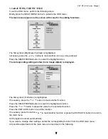
Page 7: ...window here Image Adjust is displayed The first symbol H Position is highlighted If necessary press the 6 or 5 button to mark another function Press the SELECT MENU button to select the highlighted f...

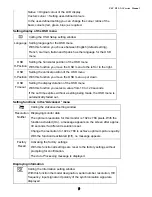
Page 8: ...the left or to the right V Position Adjusting the vertical position With this function you move the picture up or down Clock Setting synchronisation With this function you adjust the picture width to...

Page 9: ...is function you select a value from 10 to 120 seconds If the set time expires without a setting being made the OSD menu is automatically faded out Setting functions in the Advanced menu Calling the Ad...

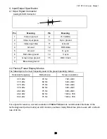
Page 10: ...o ground 4 2 Factory Preset Display Modes The following are the most frequently used of the preset operating modes Horizontal frequency Refresh rate Screen resolution 31 5 kHz 31 5 kHz 37 5 kHz 37 9 k...

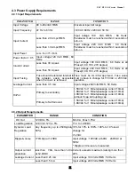
Page 11: ...oved Fuse must be UL CSA approved Fuse value must no have to change for 115 VAC or 230 VAC operation Leakage Current Less than 3 5 mA Input voltage 240 Volts RMS 50 Hertz Primary to secondary 1 5KVAC...

Page 12: ...x 0 297 W mm Display Mode Normally White Surface treatment Haze 25 Anti glare Hard Coating 3H 4 4 3 Optical Characteristics The optical characteristics are measured under stable conditions at 25 Room...

Page 13: ...two lamps are shown in the following tables Ta 25 2 ITEM SYMBOL MIN TYP MAX UNIT NOTE Lamp Current IL 3 0 6 0 6 5 mArms 1 Lamp Voltage VL 665 Vrms IL 6 0 mArms Frequency fL 40 60 KHz 2 1220 25 Startu...

Page 14: ...FSC B15 1A Service Manual 14...

Page 15: ...FSC B15 1A Service Manual 15 5 2 Software Flow Chart 1 2 N Y 5 Y N 10 Y N 12 Y N 7 Y N 6 4 3 8 9 14 11 13 Y N 15 Y N 16 17 19 Y N 18...

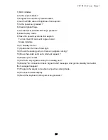
Page 16: ...e LED and set it to green color Scaler initialize 10 In standby mode 11 Update the life time of back light 12 Check the analog port are there any signals coming 13 Does the scalar send out a interrupt...

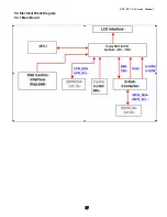
Page 17: ...FSC B15 1A Service Manual 17 5 3 Electrical Block Diagram 5 3 1 Main Board...

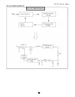
Page 18: ...FSC B15 1A Service Manual 18 5 3 2 Inverter Power Board Inverter Block Diagram...

Page 19: ...FSC B15 1A Service Manual 19 Power Block Diagram...

Page 20: ...B B CLK CLK TXD RXD VCC2 5 VAA3 VAA1 VCC12V VAA2 VCC12V 62X115 FOR SEIMENS PA 0 9 MST8031B SCHEMATIC VCPU VAA2 VAA1 DIM VCC12V C213 47uF 16V R204 10K 1 16W GND R211 10K 1 16W D201 DIODE SCHOTTKY R208...

Page 21: ...WP VCC VCC5V VGA_CON C302 NC R327 75 1 16W GNDR 4 R 4 VPLL PA2 PA9 PB 0 9 PB0 C406 0 1uF PA5 B 3 PB5 C401 0 1uF RIN 3 C413 0 1uF NC VAD R404 10K C421 0 1uF R403 390 1 16W VAA1 2 PB 0 9 C430 100pF BIN...

Page 22: ...1 16W C610 0 001uF C607 0 001uF RP602 10K 1 16W 1 2 3 4 8 7 6 5 R622 0 1 16W MENU R611 NC AUDIO_SD 7 R626 10K 1 16W R612 NC C612 0 1uF R639 10K 1 16W R617 470 1 16W HWRESET 4 C602 22pF C605 0 1uF TXD...

Page 23: ...0V F902 0 1 16W D911 31DQ10 R933 150 1 16W D903 1N4148 IC902 PC123FY2 4P 1 2 4 3 IC905 AIC1084 33CT 3 1 2 VIN ADJ Vout CN102 CONN 1 2 3 4 5 6 R930 470 1 4W R927 1K 1 4W F901 FUSE 3 3V D912 31DQ06 Q901...

Page 24: ...op Victory Electronics Co Ltd B 2 2 Tuesday October 01 2002 Title Size Document Number Rev Date Sheet of R219 470 D204 RLZ11B C225 1uF 25V R221 15K R240 51K R215 3 9K 1 16W R207 OPEN R237 620 D205 1N4...

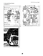
Page 25: ...FSC B15 1A Service Manual 25 7 PCB Layout 7 1 Main Board 715L1225 C...

Page 26: ...FSC B15 1A Service Manual 26...

Page 27: ...FSC B15 1A Service Manual 27 7 2 Inverter Power Board 715L1063 1A...

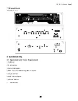
Page 28: ...pad Board 715L1071 1 2 8 Maintainability 8 1 Equirement and Tools Requirement 1 Voltmeter 2 Oscilloscope 3 Pattern Generator 4 DDC Tool with a IBM Compatible Computer 5 Alignment Tool 6 LCD Color Anal...

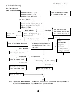
Page 29: ...CU No nothing is show Connected the Signal cable again Check LED status Check Power switch is in Power on status and check if Power switch had been stuck Led Orange OK Keyboard no stuck Led orange Led...

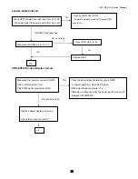
Page 30: ...esponse NG no Voltage Measured the Q203 pin 3 3 3 V Check CN201 pin 9 10 5V OK OK Replace Q203 Yes Measured the inverter connector CN201 Pin2 on off control 5V on Pin4 PWM signal control dim 0V 5V NG...

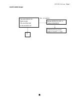
Page 31: ...ce Manual 31 4 U401 DATA Output NG no transition Replace MST8011B U401 or replace MAINBOARD Check U401MST8011B Signal output PA0 PA9 PB0 PB9 Is the waveform ok If Main Board being replace please do th...

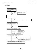
Page 32: ...t 120V or 220V NG OK Change F901 check BD901 Q903 IC901 Check the voltage of C904 Check bridge rectified circuit NG OK Check start voltage for the pin3 of IC901 Change IC901 NG Repeating the start vol...

Page 33: ...12V NG OK Change Q201 or Q202 Check the pin1 of U201 have sawtooth wave NG OK Change U201 Check D201 D202 have the output of square wave at short time NG OK Check Q205 Q207 Q203 D201 or Q206 Q208 Q20...

Page 34: ...2 3 KeyPad Board OSD is unstable or not working Is Key Pad Board connecting normally Connect Key Pad Board Is Button Switch normally Replace Button Switch Y N N Is Key Pad Board Normally Replace Key P...

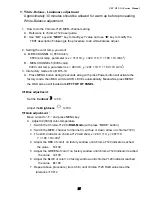
Page 35: ...utton will activate the factory mode then MCU will do AUTO LEVEL automatically Meanwhile press MENU the OSD screen will located at LEFT TOP OF PANEL 4 Bias adjustment Set the Contrast to 50 Adjust the...

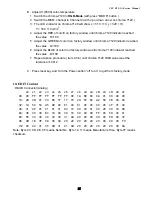
Page 36: ...B 100 7 Repeat above procedure item 4 5 6 until chroma 7120 RGB value meet the tolerance 100 2 C Press reset key and Turn the Power button off to on to quit from factory mode 10 EDIT Content D SUB Con...

Page 37: ...LABEL P 1PCS 40L 581 26668 SLZ LABEL P 1PCS 40L 581 26704 FOR CARTON PALLET P 0 05PCS 44L3548 1 EPS L P 1PCS 44L3548 2 EPS R P 1PCS 44L3548 5 U TYPE SHEET P 1PCS 44L3548624 1A CARTON P 1PCS 44L900321...

Page 38: ...4 1B CPU LABEL P 1PCS 40L 45762412A CBPC LABEL P 1PCS 44L3231508512 P 1PCS U701 56L 616 1 TDA7496L BY ST P 1PCS U601 56L1125137SB5 W78E65P 40 P 1PCS C202 67L215B221 4H LOW ESR 220UF 25V 8 11 P 1PCS C2...

Page 39: ...06 PHILIPS SMT 06 P 1PCS Q602 57L 417 6 PMBS3906 PHILIPS SMT 06 P 1PCS Q203 57L 763 1 A03401 SOT23 BY AOS A1 P 1PCS RP601 61L 125103 8 CHIP AR 8P4R 10KOHM 5 P 1PCS RP602 61L 125103 8 CHIP AR 8P4R 10KO...

Page 40: ...HIPR 10K OHM 5 1 16 P 1PCS R404 61L0603103 CHIPR 10K OHM 5 1 16 P 1PCS R405 61L0603103 CHIPR 10K OHM 5 1 16 P 1PCS R406 61L0603103 CHIPR 10K OHM 5 1 16 P 1PCS R407 61L0603103 CHIPR 10K OHM 5 1 16 P 1P...

Page 41: ...CHIPR 4 7K OHM 5 1 1 P 1PCS R207 61L0603472 CHIPR 4 7K OHM 5 1 1 P 1PCS R212 61L0603472 CHIPR 4 7K OHM 5 1 1 P 1PCS R402 61L0603472 CHIPR 4 7K OHM 5 1 1 P 1PCS R616 61L0603472 CHIPR 4 7K OHM 5 1 1 P...

Page 42: ...P 0 1UF 50V X7R P 1PCS C409 65L0603104 32 CHIP 0 1UF 50V X7R P 1PCS C410 65L0603104 32 CHIP 0 1UF 50V X7R P 1PCS C411 65L0603104 32 CHIP 0 1UF 50V X7R P 1PCS C412 65L0603104 32 CHIP 0 1UF 50V X7R P 1P...

Page 43: ...37 CHIP 1UF 50V Y5V P 1PCS FB304 71L 56G151 A TB160808G151 P 1PCS FB201 71L 56Z601 CHIP BEAD 600 OHM 0805 P 1PCS FB401 71L 56Z601 CHIP BEAD 600 OHM 0805 P 1PCS FB402 71L 56Z601 CHIP BEAD 600 OHM 0805...

Page 44: ...0 1GCJ TACT SWITCH TSPB 2 P 0PCS SW5 77L 600 1GCJ TACT SWITCH TSPB 2 P 0PCS SW1 77L 600 1GHJ KEY SWITCH P 1PCS SW2 77L 600 1GHJ KEY SWITCH P 1PCS SW3 77L 600 1GHJ KEY SWITCH P 1PCS SW4 77L 600 1GHJ KE...

Page 45: ...10 250VAC P 0PCS C213 63L210J1842A2 PMS 0 18UF 250V P 1PCS C214 63L210J1842A2 PMS 0 18UF 250V P 1PCS C213 64L180J184AAT CAP 0 18UF 160V R79 P 0PCS C214 64L180J184AAT CAP 0 18UF 160V R79 P 0PCS C905 6...

Page 46: ...OKE BY LI SHIN P 1PCS L904 73L 253 91 LS CHOKE BY LI SHIN P 1PCS L202 73L 253139 LS CHOKE P 0PCS L201 73L 253139 YL CHOKE P 1PCS L202 73L 253139 YL CHOKE P 1PCS L201 73L 253139LSL CHOKE COIL P 0PCS PT...

Page 47: ...P 1PCS R915 61L 17210052T 100HM 5 1 4W P 1PCS R929 61L 17210152T 100 OHM 5 1 4W P 1PCS R224 61L 17210252T 1K OHM 5 1 4W P 1PCS R225 61L 17210252T 1K OHM 5 1 4W P 1PCS R226 61L 17210252T 1K OHM 5 1 4W...

Page 48: ...UF 50V PEN P 1PCS C920 65L517K102 5T621 1000PF 10 Y5P 500V P 1PCS C921 65L517K102 5T621 1000PF 10 Y5P 500V P 1PCS C906 67L 309220 7T 22UF 20 50V P 1PCS C207 67L 309479 7T 4 7UF 20 50V 85 1PCS C924 67L...

Page 49: ...PCS R208 61L0603472 CHIPR 4 7K OHM 5 1 1 P 1PCS R209 61L0603472 CHIPR 4 7K OHM 5 1 1 P 1PCS R205 61L0603473 CHIP 47K OHM 1 16W P 1PCS R206 61L0603473 CHIP 47K OHM 1 16W P 1PCS R234 61L0603511 CHIPR 51...

Page 50: ...1PCS C211 65L0805105 27 CHIP 1UF 25V Y5V 0805 P 1PCS C212 65L0805105 27 CHIP 1UF 25V Y5V 0805 P 1PCS C219 65L0805105 27 CHIP 1UF 25V Y5V 0805 P 1PCS C220 65L0805105 27 CHIP 1UF 25V Y5V 0805 P 1PCS C2...

Page 51: ...CS 15L5983 1 BASE BRACKET P 1PCS 33L4602 AS L BUTTON FUNCTION P 1PCS 33L4603 1 L LENS POWER P 1PCS 33L4604AAS L CONTROL PANEL P 1PCS 33L4702 BT L STAND P 1PCS 34L1135ABT 2B FRONT PANEL P 1PCS 34L1136...

Reviews: