FSC B15-1A Service Manual
36
B
、
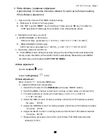
Adjust C1(6500) color-temperature
1
、
Switch the chroma-7120 to
RGB-Mode
(with press “MODE” button )
2
、
Switch the MEM .channel to Channel 4( with up or down arrow on chroma 7120 )
3
、
The LCD-indicator on chroma 7120 will show x = 313
±
10, y = 329
±
10,
Y = 180
±
10 cd/m
2
4
、
Adjust the RED of color3 on factory window until chroma 7120 indicator reached
the value R=100
5
、
Adjust the GREEN of color3 on factory window until chroma 7120 indicator reached
the value G=100
6
、
Adjust the BLUE of color3 on factory window until chroma 7120 indicator reached
the value B=100
7
、
Repeat above procedure ( item 4,5,6) until chroma 7120 RGB value meet the
tolerance =100
±
2
C
、
Press reset key and Turn the Power-button “off to on” to quit from factory mode.
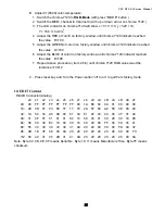
10. EDIT Content
D-SUB Connector(Analog)
x0 x1 x2 x3 x4 x5 x6 x7 x8 x9 xA
xB
xC xD xE xF
00 00 FF FF FF FF FF FF 00
1A B3 84
04
01 00 00 00
16: 2D 0D 01 03
68 1F 17
78
2A 57
84
A2 58 4E 93 24
32: 1A 50 53 A5 4E 00 61
40
61
4F
45
40
45 4F 31 40
48: 31 4F 01 01
01 01 64
19
00
40
41
00
26 30 18 88
64: 36 00 30 E4 10 00 00
18
00
00
00
FF 00 59 45 41
80: 55 30 30 30
30 30 31
0A 20
20
00
00
00 FD 00 37
96: 4B 1E 3F 08
00 0A 20
20
20
20
20
20
00 00 00 FC
112 00 42 31 35
2D 31 41
0A 20
20
20
20
20 20 00 8A
Note: Byte 0C, 0D, 0E, 0F means Serial No. Byte 10, 11 means Manufacture Time. Byte 7F means
checksum
Summary of Contents for FSC B15-1A
Page 14: ...FSC B15 1A Service Manual 14...
Page 17: ...FSC B15 1A Service Manual 17 5 3 Electrical Block Diagram 5 3 1 Main Board...
Page 18: ...FSC B15 1A Service Manual 18 5 3 2 Inverter Power Board Inverter Block Diagram...
Page 19: ...FSC B15 1A Service Manual 19 Power Block Diagram...
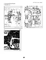
Page 25: ...FSC B15 1A Service Manual 25 7 PCB Layout 7 1 Main Board 715L1225 C...
Page 26: ...FSC B15 1A Service Manual 26...
Page 27: ...FSC B15 1A Service Manual 27 7 2 Inverter Power Board 715L1063 1A...


