background image

Color monitor MCM 17P2

A26361-K581-Z100-2-5E19

English - 11

Settings with the OSD menu

To set the OSD menu, perform the following steps:

Press the OSD button 

 to activate the OSD menu.

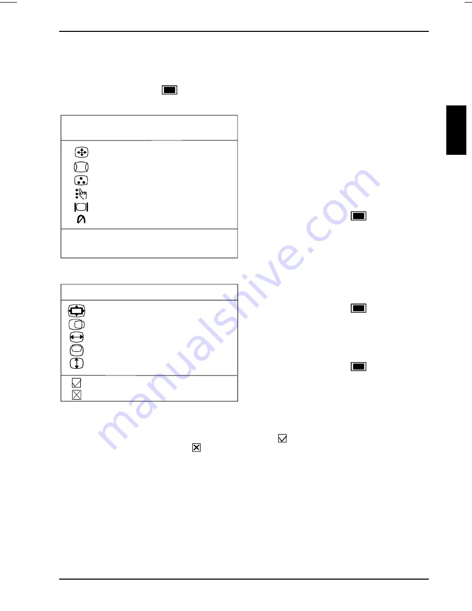
The main menu appears on the screen with icons for the setting functions.

1024 x 768   68.7KHZ  85HZ

MAIN MENU

SIZE & POSITION

GEOMETRY

COLOR TEMPERATURE

ADVANCED CONTROLS

MONITOR STATUS

DEGAUSS

EXIT OSD
RESET

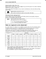
For preset modes you will find information about
the current resolution, horizontal frequency and
refresh rate in the top line.

For all non-preset modes, 

New Mode 

is

displayed.

Turn the setting control to mark the desired
submenu.

(If you wish to exit the OSD menu, select

EXIT OSD

.)

Press the OSD button 

 to select the

highlighted submenu (e. g. .

SIZE &

POSITION

).

The corresponding setting window or submenu (here: 

SIZE & POSITION

)


is displayed.

SIZE & POSITION

ZOOM

HORIZONTAL POSITION

HORIZONTAL SIZE

VERTICAL POSITION

VERTICAL SIZE

SAVE & RETURN TO MAIN MENU

RECALL

Turn the setting control to mark the desired
icon.

Press the OSD button 

 to select the

highlighted icon.

Depending on the function, a window with a
setting range or a selection menu is displayed.

Turn the setting control to make the setting.

Press the OSD button 

 to return to the

submenu.

All changes are stored automatically. The OSD menu disappears after a short time (e. g.
10 seconds). The time can be set under 

OSD TIMER

 in the 

ADVANCED CONTROLS

 menu.

The OSD menu can be hidden beforehand by selecting the 

 symbol to save your settings and to

return to the main menu. Select the 

 symbol to cancel the setting and return to the main menu.

Summary of Contents for MCM 17P2

Page 1: ......

Page 2: ...nheft Aktuelle Informationen zu unseren Produkten Tips Updates usw finden Sie im Internet http www fujitsu siemens com Is there any technical problem or other question you need clarified Please contac...

Page 3: ......

Page 4: ...0 1233 12 33...

Page 5: ...onitor Moniteur couleur Monitor de color Monitor a colori F rgsk rm Kleurenbeeldscherm Betriebsanleitung Operating Manual Deutsch English Fran ais Espa ol Italiano Svenska Nederlands TCO 99 Ausgabe Ok...

Page 6: ...oder GM Eintragung Lieferm glichkeiten und technische nderungen vorbehalten Copyright Fujitsu Siemens Computers B V 1999 VESA DDC and DPMS are registered trademarks of Video Electronics Standards Ass...

Page 7: ...hecking the contents of the consignment 6 Installing an ergonomic video workstation 6 Connecting the monitor 7 Operation of the monitor 8 Switching the monitor on 8 Switching the monitor off 9 Notes o...

Page 8: ......

Page 9: ...e screen controller graphics card of your PC It processes the data supplied to it by the screen controller The screen controller the associated driver software is responsible for setting the modes res...

Page 10: ...e the data on data carriers nearby Therefore never keep magnetic data carriers near the monitor The device automatically sets itself to the correct voltage within the range from 100 V to 120 V and 200...

Page 11: ...ds Transport the monitor with care and only in its original packaging or another corresponding packaging fit to protect it against knocks and jolts Above all never drop the monitor If the CRT is damag...

Page 12: ...a Increase the separation between equipment and the receiver Connect the equipment into an outlet on a circuit different from that to which the receiver is connected Consult the dealer or an experienc...

Page 13: ...ing the terminals in your plug proceed as follows The wire which is coloured Green and Yellow must be connected to the terminal in the plug which is marked with the letter E or by the earth symbol or...

Page 14: ...h data cable one power cable a Guarantee Booklet this Operating Manual Should you discover that the delivery does not correspond to the delivery note notify your local sales outlet immediately i It is...

Page 15: ...ting manual for details of the ports on the system unit Please note the Safety information provided in the chapter Important notes in the Operating Manual of the PC Do not cover the ventilation openin...

Page 16: ...ector of the monitor Plug the power cable into the monitor connector at the rear of the system unit Plug the power connector of the system unit into a properly grounded power outlet i When you start w...

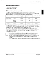
Page 17: ...o the monitor to reduce the power consumption The power indicator of the monitor changes color to indicate the status change If there is still no input power consumption is further reduced OFF mode On...

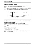
Page 18: ...escribed in the section Setting display options ADVANCED CONTROLS 1 2 3 4 1 Bright button 2 Contrast button 3 OSD button 4 Setting control on underside of monitor Adjusting the brightness and contrast...

Page 19: ...on to select the highlighted submenu e g SIZE POSITION The corresponding setting window or submenu here SIZE POSITION is displayed SIZE POSITION ZOOM HORIZONTAL POSITION HORIZONTAL SIZE VERTICAL POSIT...

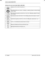
Page 20: ...etaining the side ratios Horizontal picture position HORIZONTAL POSITION Shifting the picture to the left or to the right Horizontal picture size HORIZONTAL SIZE Making the picture narrower or wider V...

Page 21: ...eft or right Calling the GEOMETRY sub menu Picture rotation ROTATION Rotating the picture in a clockwise or counter clockwise direction Pincushion distortion PINCUSHION Bending the right and left side...

Page 22: ...imary colors If you select the icon the color adjustment will be stored as the user defined color temperature Calling the COLOR TEMPERATURE sub menu 9300 K Setting color temperature 9300 K 6500 K Sett...

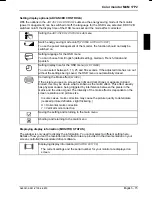
Page 23: ...the Moir effect MOIRE If the picture you see on screen has light and dark stripes or appears dull and blurred this may be due to what is known as the moir effect This effect usually has physical cause...

Page 24: ...S The factory settings are activated Notes on ergonomic color adjustment If you select colors for the display in your application programs take note of the information below The primary colors blue an...

Page 25: ...Red X 0 620 Y 0 320 Green X 0 305 Y 0 600 Blue X 0 155 Y 0 065 White X 0 283 Y 0 297 Color temperature color calibration 9300 K Gamma value 2 85 Electrical data Video analog positive 0 7 Vpp 75 Ohm Sy...

Page 26: ...Fujitsu Siemens Siemens or Siemens Nixdorf MCM 17P1 MCM 1707 MCM 1706 MCM 1705 MCM 1704 MCM 1702 Preset operating modes i The display position and size have been set to optimum values at the factory...

Page 27: ...ing Pin Meaning 1 Red video input 9 not connected 2 Green video input 10 Logic ground 3 Blue video input 11 Ground 4 Ground 12 Serial DDC data line SDA 5 DCC return 13 H sync 6 Red video ground 14 V s...

Page 28: ...construction type With different monitors the distance must be increased if necessary The screen is blank power indicator does not light Check whether the monitor is switched on Check whether the pow...

Reviews: