background image

SCALEOVIEW H22-1W/Q22W-1 


Operating of the camera 

Optional application with the Q22W-1 monitor. 
The integrated camera/video and audio channels can be connected to a PC system using the 
standard USB port integrated in the device. 


In order to ensure that the camera operates correctly with full functionality, the appropriate software 
must be installed. 
The viewing angle of the camera is 52°. The image seen by the camera can be changed by inclining 
the monitor: 


24 

A26361-K1213-Z120-1-7619, edition 1 

Summary of Contents for SCALEOVIEW H22-1W

Page 1: ...Monitor Operating Manual English SCALEOVIEW H22 1W Q22W 1...

Page 2: ...ems or other questions which you would like to be clarified Please contact our help desk see Warranty Booklet The latest information on our products tips updates etc can be found on the internet under...

Page 3: ......

Page 4: ...This manual was produced by Xerox Global Services Published by Fujitsu Siemens Computers GmbH AG 03 07 Edition 1 Order no A26361 K1213 Z120 1 7619...

Page 5: ...SCALEOVIEW H22 1W Q22W 1 Operating Manual March 2007 edition...

Page 6: ...ts including rights of translation reproduction by printing copying or similar methods in part or in whole are reserved Offenders will be liable for damages All rights including rights created by pate...

Page 7: ...cting the monitor 12 Connecting cables to the monitor 12 Connecting cables to the computer 14 Operation of the monitor 16 Adjusting rake 16 Switching the monitor on off 16 Notes on power management 17...

Page 8: ...Contents A26361 K1213 Z120 1 7619...

Page 9: ...ability power management for reducing power consumption when the computer is not in use compliance with the recommendations in accordance with TCO 03 H22 1W TCO 99 Q22W 1 In normal screen mode dark ch...

Page 10: ...u have any questions contact your sales outlet or our help desk The display surface of the LCD monitor is sensitive to pressure and scratches You should therefore be careful with the display surface s...

Page 11: ...the device Unauthorised opening and incorrect repair may greatly endanger the user electric shock fire risk You may set only those resolutions and refresh rates specified in the Technical data chapte...

Page 12: ...y cloth If the monitor is particularly dirty use a cloth which has been moistened in mild domestic detergent and then carefully wrung out CE marking CE marking for devices without radio component up t...

Page 13: ...oes cause harmful interference to radio or television reception which can be determined by turning the equipment off and on the user is encouraged to try to correct the interference by one or more of...

Page 14: ...en and are in force to assure that production units of the same equipment will continue to comply with the Commissions requirements Energy Star Guidelines The Fujitsu Siemens LCD colour monitor SCALEO...

Page 15: ...www recupel be SWICO Schweizerischer Wirtschaftsverband der Informations Kommunikations und Organisationstechnik A list of the SWICO Acceptance places can be found at http www swico ch Asien USA Taiwa...

Page 16: ...uld you discover that the delivery does not correspond to the delivery note notify your local sales outlet immediately We recommend that you keep the original packaging material You may need the packa...

Page 17: ...ands 2 Reaching area for frequently used equipment Position the keyboard where it is easiest to reach Example layout of monitor keyboard and copy holder 1 Preferable viewing sector 2 Permissible viewi...

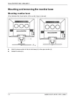
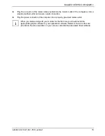
Page 18: ...removing the monitor base Mounting monitor base When delivered the lower section of the monitor base is removed Push the lower section of the monitor base 2 in the upper section 1 Fasten the screw 3...

Page 19: ...susceptible to scratching Lay the monitor on its face on a soft surface Remove the cover 3 and disconnect all cables Remove the screws 1 2 3 and 4 under the covers You can now mount a swivel arm or a...

Page 20: ...ure quality are guaranteed only if you use the data cables supplied Do not cover the ventilation openings of the monitor The computer power plug must be pulled out Be sure that the monitor and the com...

Page 21: ...d in the operating manual for your computer Connect one of the connectors of the data cable to the D SUB connector 4 or the DVI D 2 or HDMI 3 connector on the monitor and secure the plug in connection...

Page 22: ...ure it is properly engaged Plug the power cable supplied into the power connector 1 of the monitor Mount the cover over the connections A lock Kensington Lock can be mounted in the security slot 14 to...

Page 23: ...lug the power connector of the computer into a properly grounded mains outlet When you start working with your monitor for the first time you should install the appropriate graphics drivers for your a...

Page 24: ...indicator 4 Camera and microphones The ON OFF switch 2 is used for switching the monitor on and off The power indicator 3 lights up blue when the monitor and computer are switched on The power indicat...

Page 25: ...no input it sends an appropriate signal to the monitor to reduce the power consumption energy saving mode The power indicator of the monitor changes colour to indicate the status change Once an input...

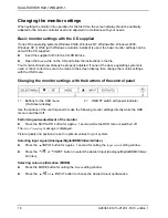
Page 26: ...ettings with the OSD menu Changing the monitor settings with the buttons of the control panel 1 Buttons for the OSD menu On Screen display 2 ON OFF switch with power indicator Use the buttons of the c...

Page 27: ...owing description default setting With the OSD function Language in the OSD Setup you can select another language i To set the OSD menu perform the following steps Press the SELECT MENU button to acti...

Page 28: ...just the value for the selected function Press the EXIT AUTO button to exit the function If necessary press the 6 or 5 INPUT button to mark another function or press the EXIT AUTO button to return to...

Page 29: ...ion If the contrast is set too high bright surfaces can no longer be distinguished from very bright surfaces If the contrast is set too low the maximum brightness will not be achieved i Adjusting size...

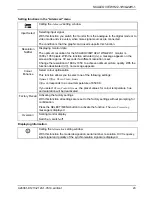
Page 30: ...ser defined setting you can change the colour ratios of the basic colours red green blue as required Setting display of the OSD menu Calling the OSD Setup setting window Language Setting language for...

Page 31: ...on deactivated Off no message appears Colour Enhance Select colour optimisation This function allows you to select one of the following settings Optimal Office Photo Video Game Office corresponds to a...

Page 32: ...e connected to a PC system using the standard USB port integrated in the device In order to ensure that the camera operates correctly with full functionality the appropriate software must be installed...

Page 33: ...nitor port on the computer Press any key on the computer keyboard the computer may be in energy saving mode Alter the brightness and or contrast until you get a picture Message No Signal Check whether...

Page 34: ...AUTO button to perform the auto adjustment of the screen Picture is wrongly adjusted Press the SELECT MENU button to activate the function Factory Recall The Auto Processing message is displayed Pict...

Page 35: ...of 1680 x 1050 has 1680 x 1050 1764000 pixels Each pixel consists of three subpixels red green and blue so there are almost 5 3 million subpixels in total In accordance with ISO 13406 2 Class II a max...

Page 36: ...B cable 2 m Storable display modes 49 Ports PC input Analogue input VGA D Sub RGB 15 pin D SUB PC Audio 3 5 mm socket Digital input DVI D HDMI DVI D 24 pin HDMI 19 pin Video input Video input Composit...

Page 37: ...x 1024 Preset operating modes The picture position and size have been set to optimum values at the factory for the operating modes listed above Depending on the screen controller used it may be necess...

Page 38: ...V Component DVI HDMI 6 1280 x 720p 50 37 500 74 250 P P PC mode w o overscan 7 1280 x 720p 50 37 500 74 250 P P HDTV Component DVI 8 1280 x 720p 60 45 150 74 250 P P PC mode w o overscan 9 1280 x 720p...

Page 39: ...onnected 23 TMDS Clock 4 not connected 14 5V Power 24 TMDS Clock 5 not connected 15 Earth 6 DDC Clock 16 Hot Plug Detect C1 Analogue R Video Out 7 DDC Data 17 TMDS Data0 C2 Analogue G Video Out 8 Anal...

Page 40: ...th 14 V sync 7 Green video earth 8 Blue video earth 15 DDC Clock Pin assignment HDMI Pin Meaning Pin Meaning 1 TMDS Data2 2 TMDS Data2 Shield 3 TMDS Data2 4 TMDS Data1 5 TMDS Data1 Shield 6 TMDS Data...

Page 41: ...SCALEOVIEW H22 1W Q22W 1 S Video port Pin Meaning 1 GND 2 GND 3 Luminance Y 4 Chrominance C A26361 K1213 Z120 1 7619 edition 1 33...

Reviews: