System expansions
Installing and removing drives
40
A26361-K520-Z300-3-7619
1
3
2
a
Ê
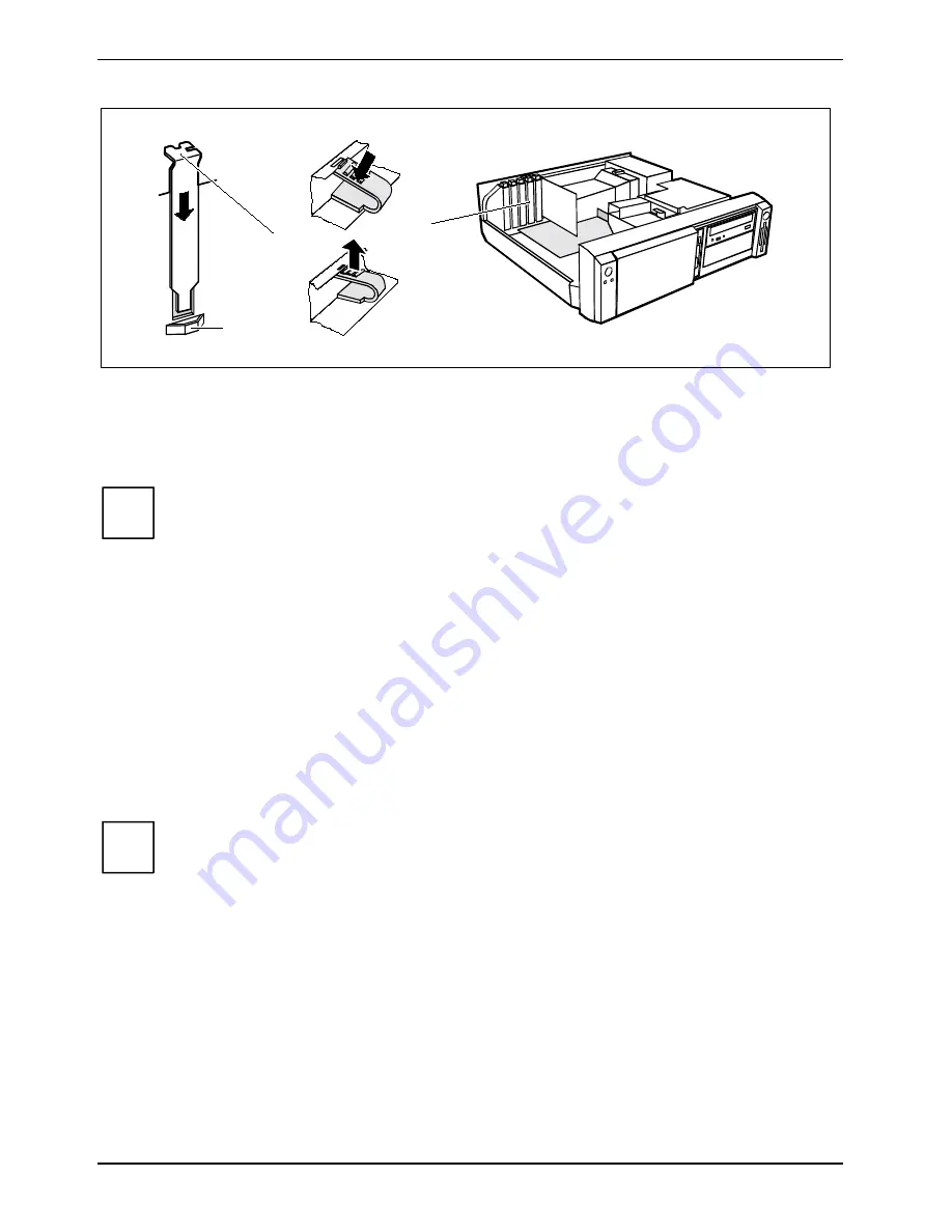
Push the rear slot cover plate into the slot (1). Ensure that the end of the cover engages into
the guide (a).
Ê
Replace the clip (2) which fixes the board. Make sure that the clip engages when released (3).
Ê
Close the casing (see "Casing, assembling").
i
If you have installed or removed a PCI board, please check the relevant PCI slot settings
in the
BIOS Setup
. If necessary, change the settings. Further information is provided in the
PCI board documentation.
Installing and removing drives
The server houses a total of three accessible drives (two 5 1/4-inch drives and one 3 1/2-inch drive)
and two non-accessible half-height 3 1/2-inch drives (Slimline).
The hard disk drives are located in the drive cage. Two different drive cages are possible.
Depending on the configuration level in your device is installed variant A or variant B. The two
variants differ as follows:
Variant A: The first and the second hard disk are secured in the drive cage with screws.
Variant B: The first hard disk is installed in the drive cage with an EasyChange carrier, the second
hard disk is secured in the drive cage with screws.
i
In the EasyChange carrier hard disks up to 5400 rpm (revolutions per minute) con be
used.
IDE drives
By default four IDE drives are supported. Ideally hard disks are connected to IDE port 1, and
accessible IDE drives, for example CD-ROMs, to IDE port 2 (see also the Technical Manual for the
system board).


