background image

SP716/SP916                                                                     3 / 20                     


WARNING 

To prevent from fire or shock hazard,do not


expose monitor to  any rain or any form of water.High voltage is 

inside the monitor so please do not remove the back cover of the cabinet if you are not a qualified monitor 
engineer.Contact the local dealer or the nearest 

Proview 

branch office if you need help. 


A.  IMPORTANT SAFETY INSTRUCTION 


Prior to using this service manual,please ensure that you have carefully followed all the procedures  outlined in 
the user's manual for this product. 

1.

  Read all of  these instructions. 

2.

  Save these instructions. 

3.

  Follow all warnings and instructions marked on the product. 

4.

  Unplug this product from the wall outlet before cleaning.Do not use liquid cleaner or aerosol 

     cleaner, use a damp cloth for cleaning. 

5.

  Do not use this product near water. 

6.

  Do not place this product on an unstable cart,stand or table.The product may fall,causing serious 

     damage to the product. 

7.

  Slots and openings in the cabinet and the back or bottom are provided for ventilation,to ensure 

     reliable operation of the product and to protect it from overheating.Those openings must not be 
     blocked or covered.The openings should never be blocked by placing the product on a bed,sofa, rug, 
     or other similar surface.This product should not be placed in a built-in installation,since proper  
     ventilation is provided.  

8.

  This products should be operated with the type of power source indicated on the marked label. 

     If you are not sure of the type of power is available, consult with your dealer or local power company.  

9.

  This product is equipped with a 3-wire grounding type plug,a plug having a third (grounding) 

      pin.This plug will only fit into a grounding-type power outlet.This is a safety feature.If you are 
      unable to insert the plug into the outlet,contact your electrician to replace your obsolete outlet.Do 
      not damage the purpose of the grounding-type plug. 

10. 

Do not allow anything to rest on the power cord.Do not locate this product where persons will walk 

      on the cord. 

11. 

Never push  any kinds of objects into this product through cabinet slots as they may touch dangerous 

      voltage points or short out parts that could result in a risk of fire or electric shock.Never spill any kinds  

of liquid on the product. 

12.

 Do not attempt to service this product yourself,as opening or removing covers may expose you to 

      dangerous voltage points or other risk.Refer all servicing to service personnel. 

13.

 Unplug this product from the wall outlet and refer servicing to qualified service personnel under the 

      following conditions. 

a. 

When the power cord or plug is damaged or frayed. 

b. 

If liquid has been spilled into the product. 

c. 

If the product has been exposed to rain or water. 

d. 

If the product does not operate normally,when the operating instructions are followed.Adjust 

    only those controls involved in the operating instructions ,since improper adjustment of  
    other controls may result in damage and will often require extra work by a qualified 
   technician to restore the product to normal operation. 

e. 

If the product has been dropped or the cabinet has been damaged. 

f. 

If the product exhibits a distinct change in performance,indicating a need for service.


Summary of Contents for SP716

Page 1: ...SP716 SP916 1 20 SP716 SP916 Service Manual...

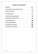
Page 2: ...ONTENTS WARNING 3 A IMPORTANT SAFETY INSTRUCTION 3 B SPECIFICATIONS 4 C TIMING CHART 6 D ADJUSTMENT PROCEDURE 8 E TROUBLE SHOOTING HINTS 9 F BLOCK DIAGRAM 13 G EXPLODED DIAGRAM 14 H SCHEMATIC DIAGRAM...

Page 3: ...able consult with your dealer or local power company 9 This product is equipped with a 3 wire grounding type plug a plug having a third grounding pin This plug will only fit into a grounding type powe...

Page 4: ...ion Auto Brightness Contrast H position V position H size Phase Reset Color selection R G B cool warm OSD Language Exit Power Source 90 264 Vac 60 50 Hz Power Consumption 48 W max Connection Type 15 P...

Page 5: ...on Auto Brightness Contrast H position V position H size Phase Reset Color selection R G B cool warm OSD Language Exit Power Source 90 264 Vac 60 50 Hz Power Consumption 50 W max Connection Type 15 Pi...

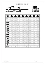
Page 6: ...0us 16 000us C Syn 3 813us 3 813us 1 270us 2 032us 3 813us 2 000us 3 200us 2 400us D Back Porch 1 907us 1 589us 3 810us 3 810us 1 907us 3 556us 2 200us 1 280us E Front Porch 0 636us 0 954us 1 016us 0...

Page 7: ...1 616us 2 092us 1 813us 1 219us 1 037us 1 067us D Back Porch 3 232us 2 462us 1 920us 2 235us 2 296us 1 837us E Front Porch 0 323us 0 369us 0 321us 0 203us 0 444us 0 119us F V 75 000Hz 60 004Hz 70 069...

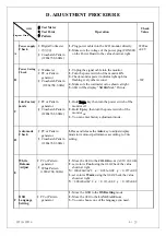
Page 8: ...de PC or Pattern generator Crosshatch Pattern 1280x768 60Hz 1 Hold Down key then turn the power switch of the monitor off 2 Hold Up key then turn the power switch of the monitor on 3 You can enter fac...

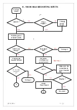
Page 9: ...splay Black LED ON Push the power ON OFF switch LED Color change Check main board U5 Pin24 Hi Lo under push power sw Back light ON To Step 2 Make sure the connection of power board is fine 12V Check t...

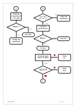
Page 10: ...sh power sw Change the power board Display Nice Job To Step 2 A Check the connection of CON1 cable Display Nice Job Change the main board Change the main board Check the main board 12V input Check the...

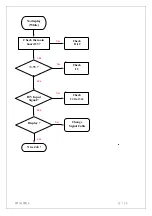
Page 11: ...SP716 SP916 11 20 NO YES NO YES NO YES NO Check the main board 3 3V input Check H V input Signal Check U3 Pin37 38 Check I2 Check 2 5 V Input Display Nice Job Change Signal Cable YES Check I1 C...

Page 12: ...SP716 SP916 12 20 NO YES NO YES NO YES NO YES No display White Check the main board 5V 3 3V H V Input Signal Check U3 Pin37 38 Display Nice Job Change Signal Cable Check I1 I2 Check I2...

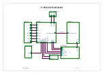
Page 13: ...D_BOARD R G B Hsync Vsync KEY ON OFF Right Left Right Left 12V 5V Bri control SDA SDA DATA CLK VCC LCD Panel CCFL DATA CLK VCC CONTROL BOARD KEY AUDIO OUT OPTION Left Right AUDIO IN OPTION Left Right...

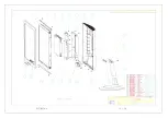
Page 14: ...SP716 SP916 14 20 G EXPLODED DIAGRAM...

Page 15: ...SP716 SP916 15 20...

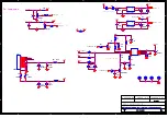
Page 16: ...SP716 SP916 16 20 H SCHEMATIC DIAGRAM...

Page 17: ...DVI_I PIGTAIL LVDS RSDS OUT Custom 1 7 Tuesday June 28 2005 Title Size Document Number Rev Date Sheet of TOP LEVEL E MSTAR COSTDWON DVI_I PIGTAIL LVDS RSDS OUT Custom 1 7 Tuesday June 28 2005 CHECK B...

Page 18: ...R10 NP R4 100 R4 100 F1 24V 5A F1 24V 5A D12 D4001 D12 D4001 C2 0 1uF C2 0 1uF 1 1 R15 100K NC R15 100K NC R1 33K R1 33K S1 S1 2 1 TC3 220uF 16V TC3 220uF 16V TC4 220uF 25V TC4 220uF 25V D11 D4001 D11...

Page 19: ...75_1 R36 75_1 D23 BAV99 D23 BAV99 3 2 1 R221 10R R221 10R R201 3 3K R201 3 3K R30 47 R30 47 C80 0 1uF C80 0 1uF C82 0 1uF C82 0 1uF R225 100 R225 100 D28 BAV99 D28 BAV99 3 2 1 R22 100 R22 100 D27 MMB...

Page 20: ...F C38 0 1uF C87 47PF C87 47PF TC8 10uF 16V TC8 10uF 16V R47 10K R47 10K C52 22pF C52 22pF C53 0 1uF C53 0 1uF C33 0 1uF C33 0 1uF R25 47R R25 47R R38 47R R38 47R R48 47R R48 47R U3 MST TSU16AK TSU56AK...

Page 21: ...4 STV2 4 OCLK 4 ECLK 4 LVB3P 4 LVB2M 4 LVB2P 4 LVACKM 4 LVACKP 4 MCU_OD_EN Title Size Document Number Rev Date Sheet of PANEL INTERFACE E MSTAR COSTDWON DVI_I PIGTAIL LVDS RSDS OUT Custom 5 7 Tuesday...

Page 22: ...D D33 ESD R70 1K R70 1K R72 10K R72 10K RN6 10K RN6 10K 1 2 3 4 5 6 7 8 C66 22pF C66 22pF RN5 10K RN5 10K 1 2 3 4 5 6 7 8 R68 10K R68 10K D34 ESD D34 ESD S9 S9 2 1 D31 ESD D31 ESD Y1 11 0592MHZ Y1 11...

Page 23: ...LC Electronic Co Ltd Copy right LIEN CHANG Electronic Enterprise Co Ltd No copy disclosure is Allowed All Right Reserved by LIEN CHANG MODEL AI 0088FAI 0088AF Spec No 01 29 239...

Page 24: ...c Co Ltd Copy right LIEN CHANG Electronic Enterprise Co Ltd No copy disclosure is Allowed All Right Reserved by LIEN CHANG 1 3 2 4 1 3 2 4 3 3 1 1 2 2 8 8 4 4 5 5 6 6 7 7 MODEL AI 0088FAI 0088AF Spec...

Page 25: ...SP716 SP916 17 20 I PCB LAYOUT DIAGRAM Main Board...

Page 26: ...SP716 SP916 18 20 Control Board Inverter Power Board Top layer...

Page 27: ...SP716 SP916 19 20 Bottom layer...

Page 28: ...SP716 SP916 20 20 MEMO...

Reviews: