SP716/SP916 8 / 20
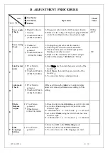
D. ADJUSTMENT PROCEDURE
ITEM
Program Menu.
﹟
Test Meter
﹡
Test Point
﹫
Pattern
Operation
Check
Value
A
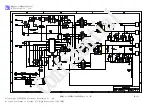
Power supply
Check
﹟
Digital Voltmeter
﹡CON 001
﹫
Crosshatch Pattern
(1280x768, 60Hz)
1.
Plug power cable into the LCD monitor directly.
2.
Make sure the voltage of the power plug (CON001)
on the
Power Board to the value shown at right.
220Vac
±0.2V
B
Power Saving
Check
﹟
Wattmeter
﹟
PC or Pattern
generator
﹫
Crosshatch Pattern
(1280x768, 60Hz)
1.
Unplug the signal cable into the monitor.
2.
Turn the power switch of the monitor
ON
.
3.
Check monitor power indicator light up blue
flashing every other second.
4.
Make sure the wattmeter value shown at right.
5.
OSD
will be display “
NO SIGNAL
” Picture.
‹ 3W
C
Into Factory
mode
﹟
PC or Pattern
generator
﹫
Crosshatch Pattern
(1280x768, 60Hz)
1.
Hold
Down
key,then turn the power switch of the
monitor
off
.
2.
Hold
Up
key,then turn the power switch of the
monitor
on
.
3.
You can enter factory adjustment mode.
D
Auto mode
Check
﹟
PC or Pattern
generator
﹫
Crosshatch Pattern
(1280x768, 60Hz)
1.
Press and release the
Auto
key to adjust display
mode to its utmost performance according to
VGA
setting.
E
White
Balance
Adjust
﹟
PC or Pattern
generator
﹫
White Pattern
(1280x768, 60Hz)
1.
Move the
OSD
to the
COLOR
mode
(
AUTO COLOR).
2.
set color is
Cool
using the
OSD
,Check the value
shown at right.
Y
= 200±20cd/m^2
x
= 0.283±0.02
y
= 0.297±0.02
3.
set color is
Warm
using the
OSD
,Check the value
shown at right.
Y
= 200±20cd/m^2
x
= 0.313±0.02
y
= 0.329±0.02
F
OSD
Language
Setting
﹟
PC or Pattern
generator
1.
Move the OSD to the
OSD setting
mode
2.
Move the
OSD
to the
LANGUAGE
mode
.
3.
You can choose one of the language you need.
Summary of Contents for SP716
Page 1: ...SP716 SP916 1 20 SP716 SP916 Service Manual...
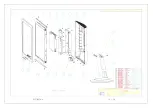
Page 14: ...SP716 SP916 14 20 G EXPLODED DIAGRAM...
Page 15: ...SP716 SP916 15 20...
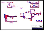
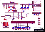
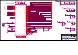
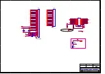
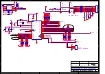
Page 16: ...SP716 SP916 16 20 H SCHEMATIC DIAGRAM...
Page 25: ...SP716 SP916 17 20 I PCB LAYOUT DIAGRAM Main Board...
Page 26: ...SP716 SP916 18 20 Control Board Inverter Power Board Top layer...
Page 27: ...SP716 SP916 19 20 Bottom layer...
Page 28: ...SP716 SP916 20 20 MEMO...

