background image

J

E

Summary of Contents for 1740
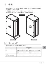
Page 1: ...J E ...

Page 2: ...パーソナル用 家庭用 通常の産業用等の一般的用途を想定して設計 製造されて いるものであり 原子力施設における核反応制御 航空機自動飛行制御 航空交通管制 大量輸送システム における運行制御 生命維持のための医療器具 兵器システムにおけるミサイル発射制御など 極めて高度 な安全性が要求され 仮に当該安全性が確保されない場合 直接生命 身体に対する重大な危険性を伴う用 途 以下 ハイセイフティ用途 という に使用されるよう設計 製造されたものではございません お客 様は 当該ハイセイフティ用途に要する安全性を確保する措置を施すことなく 本製品を使用しないでくだ さい ハイセイフティ用途に使用される場合は 弊社担当営業員までご相談ください 当社のドキュメントには 外国為替および外国貿易管理法 に基づく特定技術が含まれていることがありま す 特定技術が含まれている場合は 当該ドキュメントを輸出ま...

Page 3: ...ed Copyright FUJITSU LIMITED 2008 で示した記号は 警告 注意を促す内容であることを告げるもので す 記号の中やその脇には 具体的な警告内容が示されています で示した記号は してはいけない行為 禁止行為 であることを告 げるものです 記号の中やその脇には 具体的な禁止内容が示されて います で示した記号は 必ず従っていただく内容であることを告げるもの です 記号の中やその脇には 具体的な指示内容が示されています 記号 意味 お使いになる際の注意点や してはいけないことを記述しています 必ずお読みください ハードウェアやソフトウェアを正しく動作させるために必要なことが 書いてあります 必ずお読みください 参照ページや参照マニュアルを示しています 製品名称 本文中の表記 19 インチラック モデル 1740 19R 174A1 19R 174B1 19R 174...

Page 4: ...2 搬入時の留意事項 8 2 3 設置 運用時の留意事項 9 3 ラックの構成と設置 12 3 1 構成 12 3 2 フロントドアの開き方 14 3 3 リヤドアの開き方 15 3 4 ラックの設置 16 3 5 ラックの連結 18 4 ラック設置後の取り扱いについて 25 4 1 ケージナット取り付け 取り外し手順 25 4 2 扉回転軸位置の変更手順 29 4 3 汎用テーブル 固定式 の取り付け 47 4 4 汎用テーブル 可動式 の取り付け 55 4 5 ケーブルホルダの取り付け手順 64 4 6 ブランクパネルの取り付け手順 66 ...

Page 5: ...IA19 インチラック規格 ユニバーサルピッチ 19 インチラック モデル 1740 の外観イメージを以下に示します 1 1 ラインナップ 本ラックのラインナップは次の表のとおりです モデル 1740 収容ユニット数 40U 型名 転倒防止用スタビライザ付き 転倒防止用スタビライザ無し 基本ラック 19R 174A1 増設ラック 19R 174B1 基本ラック 19R 174A2 増設ラック 19R 174B2 サイズ 幅 奥行 高さ mm 700 1272 2000 700 1050 2000 ࡕ 㧝㧣㧠㧜 㧝㧥㧾㧙㧝㧣㧠㧭㧞 㧝㧥㧾㧙㧝㧣㧠㧭㧝 ...

Page 6: ...きません 下 記のラックに搭載可能です MC R7RC11 MC R7RC21 MC R7RC12 MC R7RC22 MC R8RC11 MC R8RC21 MC R8RC12 MC R8RC22 設置方法により添付品の選択が可能 設置方法に合わせて 転倒防止用スタビライザ添付の有無が選べます ラックの中心に装置を搭載 従来のスタンダードラックやグローバルラックは 正面から見て右寄りに装置を配置して いましたが 本ラックでは装置搭載エリアをラックの中心に配置しました これにより 片側にケーブルが集中することなく ケーブル配線が容易となります ケーブルホルダを標準搭載 ラック内部のケーブルルートにケーブルホルダを標準搭載しており ケーブルマネージメ ントが容易になります 冷却性能向上 前後扉の開口率を 80 とし 冷却性能を向上しました 従来のスタンダードラックやグ ローバルラックは開口率...

Page 7: ...装置 ラックの固定などの地震対策が 必要です 床の強度が弱い場所に設置しないでください 最大搭載時の最大重量は 1000Kg 程度になるため 強度が弱い床では床が抜け る可能性があります ラックシステムの正常な稼動 保守を容易にするために 設置エリアを確保し てください ラックの上または近くに 花びん 植木鉢 コップ などの水の入った容器 金属物を置かないでください 故障 火災 感電の原因となります 湿気 ほこり 油煙の多い場所 通気性の悪い場所 火気のある場所に置かな いでください 故障 火災 感電の原因となります 直射日光の当たる場所や 暖房器具の近くなど 高温になる場所には設置しな いでください また 10 未満の低温になる場所には 設置しないでください 故障の原因になります ラックの開口部 通風孔など をふさがないでください 通風孔をふさぐと内部に熱がこもり故障や火災の原因となりま...

Page 8: ...重量が搬入する装置重量以上でも使用できることを事前に確認してくだ さい 装置搬入時は 転倒防止のためラック高さ方向の半分よりも下を押してください 本ラックに搭載する装置によっては 重心位置が高い場合があります また 側面からは押さないでください 転倒するおそれがあります 前扉の中央付近 吸気口部分を押すと扉が変形するおそれがありますので 扉の角を押 してください ラック搭載の本体製品を寒い場所から暖かい部屋へ搬入すると 製品内部が結露しま す 1時間当たりの温度上昇が 15 を超えないように室温調整を行い 結露を発生させな いようにしてください 結露の発生に関しては 次の表を参考にしてください 室内温度 備考 10 15 20 25 30 35 40 相対湿度 20 7 5 3 1 5 9 13 例 温度 25 で湿度 60 の場合 装置が 17 以下のとき 結 露します 40 3 2 7...

Page 9: ...失しないように管理を徹底してください 鍵 はラックに貼り付けられている場合 下図参照 と 添付品が入れられた箱に同梱され ている場合があります 2 3 設置 運用時の留意事項 通気 保守エリアの確保 ラックを設置するときは 放熱と保守用にスペースが必要です 次のスペースを確保してください ਛ G EN QUGU ⴼ ࡈࡠࡦ ࠕ 䌛 ࠢߦ ࠅઃߌࠄࠇߡ ࠆ႐ว䌝 ࠢ೨㕙ⷞ OO OO OO OO OO OO OO OO OO OO OO OO ࠢ 㕙ⷞ ࠢ೨㕙 ㅢ ޔ ࠛ ࠕ ...

Page 10: ...さい ラックの転倒防止 注意 スタビライザの取り付け手順については 3 4 ラックの設置 を参照してください ラックはボルト等で床 スラブ に固定してください 固定しない場合 250 ガル を超える地震が発生したとき ラックが転倒するおそれ があります ラックが転倒した場合 死亡または重症を負うおそれがあります またラック内の 機器や周囲のものが破損するおそれがあります ラック型名 耐震キット型名 基本ラック 19R 174A2 19R 17ST1 増設ラック 19R 174B2 19R 17ST2 スタビライザ付きラックの場合 ラック設置時に スタビライザは必ず取り付 けてください 取り付けない状態でラック内部の装置を引き出すと ラックが 転倒するおそれがあります スタビライザ無しラックの場合 必ずラックを固定設置して下さい 固定設置しない場合 ラックが転倒するおそれがあります ᧄ 㕙 ...

Page 11: ...の取り付け手順 を参 照してください その他の留意事項 注意 ブランクパネルを装置未搭載部に取り付けないと 排気が吸気面に回り込んで 装置の故障や寿命を短縮するおそれがあります ラックのフロントドア リヤドアは取り外さないでください 扉は重量がある ため 倒れたり 落下したりしてけがの原因となることがあります 取り外す必要が生じた場合には 弊社担当保守員にご連絡ください ラック設置後にラックを移動する場合は 必ず弊社担当営業員または担当保守 員にご連絡ください 不用意に移動すると ラックが損傷することがあります ラックに登ったり寄りかかったりしないでください 転倒などの事故のおそれ があります ...

Page 12: ...ズ WxDxH mm 700 x 1272 転倒防止用スタビライザ込み ラック本体 1050 x 2000 搭載最大 質量 kg ラック総質量 943kg 注 1 搭載総質量 800kg ラック本体除く ラック本体 143kg 転倒防止用スタビライ ザ含む ラック総質量 910kg 注 1 搭載総質量 800kg ラック本体除く ラック本体 110kg 転倒防止用スタビライザ 含む セキュリ ティ 前後扉にキーロックあり ハンドルロックにはキー操作が必要です 付属品 前扉 後扉 サイドカバー 2 枚組 ラッ クに取付け済 ラック扉用キー 2 個 転倒防止用スタビライザ 1 枚 前用 ケージナット ネジ ワッシャー組込済 各 50 個 工場搭載装置で使用した場合は その残り の数量のみ添付 ケージナット工具 ブランクパネル 1U 3 枚 2U 5 枚 3U 3 枚 ケーブルホルダ 24 個 ...

Page 13: ...ニット数 40U サイズ WxDxH mm 700 x 1050 x 2000 搭載最大 質量 kg ラック総質量 935kg 注 1 搭載総質量 800kg ラック本体除く ラック本体 135kg ラック総質量 902kg 注 1 搭載総質量 800kg ラック本体除く ラック本体 102kg セキュリ ティ 前後扉にキーロックあり ハンドルロックにはキー操作が必要です 付属品 前扉 後扉 サイドカバー 2 枚組 ラックに取付け済 ラック扉用キー 2 個 ケージナット ネジ ワッシャー組込済 各 50 個 工場搭載装置で使用した場合は その残り の数量のみ添付 ケージナット工具 ブランクパネル 1U 3 枚 2U 5 枚 3U 3 枚 ケーブルホルダ 24 個 ラックに取付け済 取扱説明書 前扉 後扉 ラックに取付け済 注 2 ラック扉用キー 2 個 連結キット 1 式 ケージナット ネ...

Page 14: ...14 3 2 フロントドアの開き方 1 扉用キーを回し ラックハンドルを持ち上げ 手前に引きます 注意 フロントドアを閉めるときは 搭載装置を完全に固定したあとに行ってください 地震が発生した場合 装置が飛び出し破損するおそれがあります ...

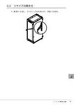
Page 15: ...3 ラックの構成と設置 15 J 3 3 リヤドアの開き方 1 扉用キーを回し ラックハンドルを持ち上げ 手前に引きます ...

Page 16: ...の場合は スタビライザを取り付けます スタビライザ無しラックの場合は レベリングフットを使って固定するか 耐震キットを 取り付けて固定します 3 4 1 スタビライザ付きラックの設置 ラックには前面側に取り付ける転倒防止スタビライザ 安定板 が基本で添付されていま すので 図のように取り付けて下さい 警告 ラック設置時に スタビライザは必ず取り付けてください 取り付けない状態 でラック内部の装置を引き出すと ラックが転倒するおそれがあります ขࠅઃߌ ...

Page 17: ...フットを使用した固定 レベリングフット底面にあいている M20 深さ 17mm のネジ穴を使用して 床に固定しま す 耐震キットを使用した固定 以下に耐震キットの取り付け手順を示します 1 ラックの前後左右の面に 耐震キットを取り付けます 耐震キットはオプション品です 2 前面 側面の金具を 3 本のボルトで 背面の金具を 2 本のボルトでラッ クに取り付けます 3 耐震キットを床に固定します 1 前面と背面の金具は 2 本のボルトで床に固定します 2 側面のスタビライザは 3 本のボルトで床に固定します ᧄߩࡏ ߢ ቯ ೨㕙 㕙 ᧄߩࡏ ߢ ቯ 㕙 ...

Page 18: ...ます プラスドライバ 2 番 3 番 六角ボルト用レンチ M8 用 呼び 13 M12 用 呼び 19 なお 高所での作業が必要ですので 脚立をご準備ください ラックの連結を行う場合は サーバ本体および周辺装置の電源を切り 電源 ケーブルをコンセントから取り外してください 感電したり機器が故障するおそれがあります ラックの連結を行う場合は 必ず 2 人以上で行ってください けがの原因となります ラック上部で行う作業の際 脚立の上に乗る場合があります 落下にご注意ください ラックの連結を行うとき ラックに足をのせないでください 品 名 数 量 備考 上部連結金具 1 下部連結金具 2 連結用パッキン 2 M12 ボルト 4 上部連結用 M8 ボルト 4 下部連結用 ...

Page 19: ...3 ラックの構成と設置 19 J 以下にラックの連結方法を示します 例 基本ラックの右側へ増設する場合 1 既設ラックのサイドカバーを取り外します サイドカバーを固定している M6 ネジ 8 本を外して サイドカバーを取り外しま す ここで取り外した M6 ネジは 後で使用しますので紛失しないようにご注意くだ さい ࠨࠗ ࠞࡃ 㧹㧢ࡀࠫ ...

Page 20: ...側耐震キットを取り外します 連結側耐震キット 側面 のラックおよび建屋床面を固定しているネジまたはボル トをすべて取り外し 耐震キット 側面 を取り外します また耐震キット 前面 背面 のラック側固定ボルトの内 連結側ボルトを各1本 取り外します ここで取り外した耐震キット 側面 およびボルトは 後で使用しますので紛失 しないようにご注意ください ᑪደᐥ㕙 ቯࡏ 㔡ࠠ 㕙 ㅪ ࡏ ࠢ ቯࡏ 㔡ࠠ 㧔 㕙㧕 㔡ࠠ ೨㕙 ㅪ ࡏ ...

Page 21: ...3 ラックの構成と設置 21 J 3 連結パッキンを貼り付けます 連結パッキンの保護紙を剥がして連結面のフレームに ラックの上部から貼り付け ます ラック前側と背面側2ヶ所に貼り付けます 4 既設ラックと増設ラックの高さを合わせます 既設ラックの横に増設ラックを並べ 増設ラックのレベルフットを調節し 既設 ラックと高さを合わせます ࡈ ࡓ ㅪ ࡄ ࠠࡦ ࡈ ࡓ ...

Page 22: ... 増設ラック用耐震キット 前面 背面 および既設ラックから取り外した耐震キッ ト 側面 を増設ラック取り付けます ボルトは耐震キットに添付のものおよび既 設ラックから取り外したものを使用します 連結金具取付け後 本締めしますの で ここでの作業は仮留めとします なお 耐震キット 前面 背面 はラックとの固定部がそれぞれ3ヶ所あります が 既設側ラックに最も近い側のそれぞれ1ヶ所は連結金具と共締めしますので 後で取り付けます 次ページを参照ください ขઃߌࡏ ขઃߌࡏ ...

Page 23: ...プカバー部の作業は高所作業となりますので注意してください またそ の際 ラックに足を乗せるなどの行為は大変危険ですので 絶対に行わない でください 下部連結金具2個 ラックの下部 前側と後側 をそれぞれ M8 ボルト 2 本で固定 します M8 ボルトは耐震キット用を共用します 耐震キットがない場合 連結キット添付 の M8 ボルトを使用します 注 耐震キットが取り付けられている場合 M8 ボルトは耐震キット用と共用とな りますので 連結キット添付のボルトは余剰となります 仮止めしていたボルトを本締めしてください ㇱㅪ ౕ 㧹㧝㧞ࡏ 㧹㧤ࡏ ਅㇱㅪ ౕ ...

Page 24: ...24 7 増設ラックにサイドカバーを取り付けます 最後に 既設ラックから取り外したサイドカバーを 既設ラックから取り外した M6 ネジで取付けます これでラックの連結作業は終了です ࠨࠗ ࠞࡃ 㧹㧢ࡀࠫ ...

Page 25: ...5 J 4 ラック設置後の取り扱いについて この章では ラック設置後の取り扱いについて説明します 4 1 ケージナット取り付け 取り外し手順 4 1 1 取り付け手順 1 ケージナットをラック内側より取り付けます ケージナットの一方の爪 を ラックのケージナット取り付け穴に引っ掛けます 図は下側に引っ掛けた場合をあらわしています 2 ケージナット工具先端の爪をケージナット取り付け穴の手前から挿入し ケージナットのもう一方の爪に嵌合させます ...

Page 26: ...手順 1 工具先端をケージナットの爪とラック柱の間に挿入して 工具の先端に近 い位置を指でつかみ ケージナットの爪を押し込みます 工具あるいはマイナスドライバを押し下げる前に ナットの爪とラック柱の間 に工具の先端あるいはマイナスドライバの先端が完全に押し込まれていること を確認してください 押し込みが不十分な場合 工具あるいはマイナスドライ バの先端が外れ けがの原因となることがあります ケージナットがラック内に落ちないようテープ等で養生してください 手で保 持する場合はケージナットの左右を持つようにしてください ...

Page 27: ...いて 27 J 注意 2 工具を押し下げて取り外します ケージナットを落とさないよう注意してください 増設 移設作業時にも本工具が必要となりますので 大切に保管してください マイナスドライバを使った手順 注意 指定位置より先端をつかまないでください 押し込み時に指がラックに当たり ケガをする原因になります ケージナットがラック内に落ちないようテープ等で養生してください 手で保 持する場合はケージナットの左右を持つようにしてください ...

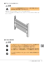
Page 28: ...28 1 マイナスドライバの先端をケージナットの爪とラック柱の間に挿入して ケージナットの爪に押し込みます 2 マイナスドライバを押し下げて取り外します ...

Page 29: ...ける作業を多数行います 取り付 けや取り外しで部品の変形 破損 紛失が発生しないように十分注意して作業してくださ い 取り外した部品は必ず再使用します 余剰は発生しません またラックに予備部品は添付 されていませんのでご注意願います 部品の取り外し 取り付けにある程度のカが必要な 場合があります 作業にあたってはご注意願います 以下の作業には プラスドライバ 2 番 やマイナスドライバなどの工具が必要です 4 2 1 前扉の軸位置変更手順 1 ラックから扉を取り外します 扉を開け 上下 2ヶ所にあるヒンジセットのそれぞれ下側のネジを緩め 下側ヒン ジを下に下げてください ネジは緩めるだけでよく 取り外す必要はありません ...

Page 30: ...30 2 次に M5 六角ネジを外し ストッパワイヤの固定を取り外します 外したネジとワイヤは 後で使用しますので紛失しないようにご注意ください 扉全体を持ち上げ 扉を取り外します この時 扉とラックの隙間に指などを挟ま ないように注意してください ⷺࡀࠫ ਅ ࡅࡦࠫ ࠬ ࡄࡢࠗࡗ ࡅࡦࠫ ਅ ࡅࡦࠫ ቯࡀࠫ 㧔 ਅ ࡩᚲ㧕 ...

Page 31: ...4 ラック設置後の取り扱いについて 31 J 3 ラック側の金具類を取り外します M5 ネジを外し 上下 2ヶ所のヒンジ ASSY を取り外します ヒンジ ASSY に固定 されているヒンジスペーサも同時に外れます M5 サラネジを外し 上中下 3ヶ所のロッド棒受金具を取り外します ࡅࡦࠫ 55 ࡅࡦࠫࠬࡍ ࠨ ࡠ ฃ ౕ ࡀࠫ 㧔 ਅ ࡩᚲ㧕 ࠨ ࡀࠫ 㧔 ਛਅ ࡩᚲ㧕 ...

Page 32: ...と左右反転した位置に取り付けま す ヒンジ ASSY は M5 ネジで ロッド棒受金具は M5 サラネジで固定します それぞれのネジは ネジ山を刻みながら締め付けていくセルフタッピングネジのた め 締め付けの際にある程度の力が必要です ヒンジ ASSY とロッド棒受金具が取り付け後の状態になっていることを確認してく ださい ࠨ ࡀࠫ 䴿 ࠨ ࠗ ࠞ ࡃ 䳦 䵀 ࡠ ฃ ౕ ࡅࡦࠫ 55 㧔 ਅ ࡩᚲ㧕 ࡀࠫ 㧔 ਛਅ ࡩᚲ㧕 㧔ขࠅઃߌᓟߩ ᘒ㧕 䴿 ࠨ ࠗ ࠞ ࡃ 䳦 䵀 㧔ขࠅઃߌᓟߩ ᘒ㧕 ...

Page 33: ...外します 上下にあるロッド棒サポータにマイナスドライバを真横から差し込み サポータを すべて取り外します 上側のロッド棒が作業者側へ倒れてくる可能性がありますので注意してくださ い ドアハンドル上下にある M5 ネジを外します ドアハンドルとロッド棒を同時に扉から取り外します M4 ネジを外し 富士通ロゴを取り外します M4 ネジを外すときに富士通ロゴが 落下する可能性がありますので 手を添えて外してください ࡠ ࠕࡂࡦ ࡀࠫ ࡠ ࠨࡐ 㧔 ਅ ࡩᚲ㧕 ࡠ ࡀࠫ ን ㅢࡠࠧ ࡑࠗ ࠬ ࠗࡃ ᚺ ࠕࡂࡦ ...

Page 34: ...す ドアハンドルとロット棒を固定している M3 バインドネジを外し ロッド棒を取り 外します スペーサも同時に外れます スペーサを無くさないように注意してください ロッド棒先端の曲げ部分が左側に向くようにして ハンドルの右側にロッド棒上 短 を M3 バインドネジとスペーサで固定します ロッド棒は上下で長さが異なります 上になるロッド棒が下になるロッド棒より 長さが短くなります ࠬࡍ ࠨ ࡃࠗࡦ ࡀ ࠫ ࡠ ਅ 㐳 ࡠ ࡠ ਅ 㐳 ࡠ 㧔 㧕 㧔ಽ 㧕 ...

Page 35: ... ラック設置後の取り扱いについて 35 J 7 ドアハンドルおよびロッド棒を取り付けます この作業を開始する前に扉の上下を反転します ドアハンドルとロッド棒の組立品を扉の表からロッド棒上 短 が上になるように 差し込みます ドアハンドルを M5 ネジにて固定します ロッド棒上下をロッド棒サポータにて固定します ࡠ ਅ 㐳 ࠕࡂࡦ ࡠ ᚺ ࡀࠫ ࡠ ࠕࡂࡦ ࡠ ࠨࡐ 㧔ขࠅઃߌᓟߩ ᘒ㧕 㧔 ਅ ࡩᚲ㧕 ...

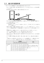
Page 36: ...36 8 富士通ロゴを取り付けます 富士通ロゴを扉の裏から M4 ネジで固定します 標準的な取り付け位置は 横方向寸法が 103 縦方向寸法が 122 です ࡀࠫ ን ㅢࡠࠧ ...

Page 37: ...す 本締めはラック側にワイヤを 取り付けるときに行います 次にヒンジの位置を調整します 上側ヒンジは扉の取り外し工程で緩んだままと なっていますので 下側いっぱいに下げて固定ネジを締め 傾かないように本締め 固定します 上側ヒンジを固定ネジで締め付ける際 下側ヒンジに突き当てるように締め付け てください 次に下側ヒンジの固定ネジを緩め ヒンジを下側いっぱいに移動します 下側ヒンジの固定ネジは扉をラックに取り付けた後に本締めしますので ここでは 締め付けません ࠬ ࡄࡢࠗࡗ ᚺ ࠃࠅ ࠆ ࡅࡦࠫ ⷺࡀࠫ ਅ ࡅࡦࠫ ࡅࡦࠫ ࡅࡦࠫ ቯࡀࠫ ᧄ ቯ 㧔 ਅ ࡩᚲ㧕 ᚺⵣࠃࠅ ࠆ ...

Page 38: ...ください 下側ヒンジを上側にスライドし ヒンジ ASSY のピンに差し込み 固定ネジを締め つけて固定します ヒンジ ASSY と上側ヒンジおよび下側ヒンジの隙間が同じであ ることを目視確認します 隙間に違いがある場合は 下側ヒンジまたはヒンジ ASSY の取り付け位置を調整し てください ストッパワイヤを M5 六角ネジでフレームに取り付け固定します また仮留めして いた扉側のワイヤ固定ネジを本締めします ストッパワイヤを固定するネジの締め付けは 扉を開け ワイヤが引っ張られた 状態で行ってください 以上で前扉の回転軸位置変更作業は終了です ⷺࡀࠫ ࠬ ࡄࡢࠗࡗ ࡅࡦࠫ 55 ߩࡇࡦ ࡅࡦࠫ 55 ࡅࡦࠫ ਅ ࡅࡦࠫ 㓗㑆ߩ 㧔 ਅ ࠞᚲ㧕 ...

Page 39: ...から扉を取り外します 扉を開け 上下 2ヶ所にあるヒンジセットのそれぞれ下側のネジを緩め 下側ヒン ジを下に下げてください ネジは緩めるだけでよく 取り外す必要はありません 2 次に M5 六角ネジを外し ストッパワイヤの固定を取り外します 外したネジとワイヤは 後で使用しますので紛失しないようにご注意ください 扉全体を持ち上げ 扉を取り外します この時 扉とラックの隙間に指などを挟ま ないように注意してください ࠬ ࡄࡢࠗࡗ ⷺࡀࠫ ࡅࡦࠫ ਅ ࡅࡦࠫ ਅ ࡅࡦࠫ ቯࡀࠫ 㧔 ਅ ࠞᚲ㧕 ...

Page 40: ...40 3 ラック側の金具類を取り外します M5 ネジを外し 上下 2ヶ所のヒンジ ASSY を取り外します ヒンジ ASSY に固定 されているヒンジスペーサも同時に外れます M5 サラネジを外し 上中下 3ヶ所のロッド棒受金具を取り外します ࡅࡦࠫࠬࡍ ࠨ ࡀࠫ ࡅࡦࠫ 55 㧔 ਅ ᚲ㧕 ࡠ ฃ ౕ ࠨ ࡀࠫ 㧔 ਛਅ ࡩᚲ㧕 ...

Page 41: ...す 手順 3 で取り外した金具類を標準取り付け位置と左右反転した位置に取り付けま す ヒンジ ASSY は M5 ネジで ロッド棒受金具は M5 サラネジで固定します それぞれのネジは ネジ山を刻みながら締め付けていくセルフタッピングネジのた め 締め付けの際はある程度の力が必要です ヒンジ ASSY とロッド棒受金具が取り付け後の状態になっているか確認してくださ い ࡅࡦࠫ 55 ࡀࠫ 㧔 ਅ ࠞᚲ㧕 ࡠ ฃ ౕ ࠨ ࡀࠫ 㧔 ਛਅ ࡩᚲ㧕 㧔ขࠅઃߌᓟߩ ᘒ㧕 㧔ขࠅઃߌᓟߩ ᘒ㧕 ...

Page 42: ...42 5 扉からドアハンドル ロッド棒付き を取り外します 上下にあるロッド棒サポータにマイナスドライバを真横から差し込み サポータを すべて取り外します 上側のロッド棒が作業者側へ倒れてくる可能性がありますので注意してくださ い ドアハンドル上下にある M5 ネジを外します ドアハンドルとロッド棒を同時に扉から取り外します ࡠ ࠕࡂࡦ ࡠ ࠨࡐ ࡑࠗ ࠬ ࠗࡃ 㧔 ਅ ࡩᚲ㧕 ࡀࠫ ᚺ ࠕࡂࡦ ࡠ ...

Page 43: ...いているロッド棒を組替えます ドアハンドルとロッド棒を固定している M3 バインドネジを外し ロッド棒を取り 外します スペーサも同時に外れます スペーサを無くさないように注意してください ロッド棒先端の曲げ部分が右側に向くようにして ハンドルの左側にロッド棒上 短 を M3 バインドネジとスペーサで固定します ロッド棒は上下で長さが異なります 上になるロッド棒が下になるロッド棒より 長さは短くなります ࡠ ࡠ ਅ 㐳 ࠬࡍ ࠨ ࡃࠗࡦ ࡀ ࠫ ࡠ ਅ 㐳 ࡠ ಽ ...

Page 44: ...が上になるように 差し込みます ドアハンドルを M5 ネジで固定します ロッド棒上下をロッド棒サポータで固定します 8 ストッパワイヤを扉に取り付け 上下 2ヶ所のヒンジセットの位置を調整 します ストッパワイヤを M5 六角ネジで扉に仮留めします 本締めはラック側にワイヤを 取り付けるときに行います 次にヒンジの位置を調整します 上側ヒンジは扉の取り外し工程で緩んだままと なっていますので 下側いっぱいに下げて固定ネジを締めて傾かないように本締め 固定します ᚺ ࡠ ਅ 㐳 ࠕࡂࡦ ࡠ ࡠ 㧔ขࠅઃߌᓟߩ ᘒ㧕 ࡠ ࠨࡐ 㧔 ਅ ࠞᚲ㧕 ࠕࡂࡦ ࡀࠫ ...

Page 45: ... ラック設置後の取り扱いについて 45 J 上側ヒンジを固定ネジで締め付ける際 下側ヒンジに突き当てるように締め付け てください 次に下側ヒンジの固定ネジを緩め ヒンジを下側いっぱいに移動します 下側ヒンジの固定ネジは扉をラックに取り付けた後に本締めしますので ここでは 締めつけません ⷺࡀࠫ ࡅࡦࠫ ቯࡀࠫ ࡅࡦࠫ ࡅࡦࠫ ᚺ ࠃࠅ ࠆ ࠬ ࡄࡢࠗࡗ ᧄ ቯ ਅ ࡅࡦࠫ 㧔 ਅ ࠞᚲ㧕 ᚺⵣࠃࠅ ࠆ ...

Page 46: ...ください 下側ヒンジを上側にスライドし ヒンジ ASSY のピンに差し込み 固定ネジを締め つけて固定します ヒンジ ASSY と上側ヒンジおよび下側ヒンジの隙間が同じであることを目視確認し ます 隙間に違いがある場合は 下側ヒンジまたはヒンジ ASSY の取り付け位置を調整し てください ストッパワイヤを M5 六角ネジでフレームに取り付け固定します また仮留めして いた扉側のワイヤ固定ネジを本締めします ストッパワイヤを固定するネジの締め付けは 扉を開けワイヤが引っ張られた状 態で行ってください 以上で後扉の回転軸位置変更作業は終了です ࠬ ࡄࡢࠗࡗ ࡅࡦࠫ 55 ࡅࡦࠫ 55 ߩࡇࡦ ࡅࡦࠫ 㧔 ਅ ࡩᚲ㧕 ⷺࡀࠫ ਅ ࡅࡦࠫ 㓗㑆ߩ ...

Page 47: ...けは 以下の手順で行います 1 ケージナットを取り付ける 2 リヤブラケットを取り付ける 3 テーブルを取り付ける 4 3 1 ケージナットの取り付け ケージナットをラックの柱 前後 に取り付けます ケージナットの取り付け方法につい ては 4 1 1 取り付け手順 を参照してください 1 フロントドアを開け 前側のラックの柱に M6 ケージナットを取り付けま す 取り付け位置はテーブル搭載位置 1U の高さ のロケーション線間にある角穴 3ヶの上下 2ヶ所 左右合計 4ヶ所となります 汎用テーブル 固定式 型名 19R 16TR1 構成品 数量 テーブル 1 リヤブラケット L 1 リヤブラケット R 1 M6 ケージナット 8 M6 ボルト 4 M6 ネジ 8 ベルト 2 取り付け手順書 1 ...

Page 48: ...48 2 リヤドアを開け 後側のラックの柱に M6 ケージナットを取り付けます 取り付け位置はテーブル搭載位置 1U の高さ のロケーション線間にある角穴 3ヶの上下 2ヶ所 左右合計 4ヶ所となります ...

Page 49: ...でずれないようにして ください 4 3 2 リヤブラケットの取り付けとテーブルの仮置き 1 4 3 1 ケージナットの取り付け 手順 2 で取り付けた後側の M6 ケージ ナットを利用して リヤブラケット R とリヤブラケット L をラックの柱 に仮固定します 固定には M6 ネジを使用します 次の手順 2 で リヤブラケット L とリヤブラケット R にテーブルを載せます テーブルを載せた際に落下しない程度に仮固定してください リヤブラケット L リヤブラケット R の取り付け向きに注意してください ...

Page 50: ...ーブル前面の仮置き用曲げを 4 3 1 ケージナットの取り付け 手順 2 で取り付けた M6 ケージナットの直上の角穴に差し込み 角穴下面に載 せてください 後ろ側は手順 1 にて取り付けたリヤブラケット L リヤブラケット R の上に載せて ください 3 仮置き用曲げを差し込んだ角穴が左右で同じ高さであるか確認してくださ い 仮置き状態ですので テーブルの上に物を載せるなどの荷重がかかる行為はしな いでください ...

Page 51: ... ケージナットの取り付け 手順 2 で取り付けた M6 ケージナット に M6 ネジを使ってテーブルを固定します リヤブラケット L リヤブラケット R がテーブルを載せても落下しないか 確認 してから作業をしてください テーブルを仮置きする際 前側は仮置き用曲げが角穴に対して十分差し込まれ確 実にテーブルが載るようにしてください また 後側はリヤブラケット L リヤ ブラケット R にテーブルが確実に載るようにしてください なお テーブルを固定するまでは支える手を離さないようにしてください ...

Page 52: ...押し付けて固定 してください A 方向 リヤブラケット L リヤブラケット R をテーブルにしっかりと押し付け 隙間が ないようにして固定してください B C 方向 リヤブラケット L リヤブラケット R をしっかり押し付けられない場合は 印の M6 ネジを少し緩めてから固定してください 䊁䊷䊑䊦 䊤䉾䉪䈱ᩇ 䊤䉾䉪䈱ᩇ 㪘 㪙 㪚 㪘 㪚 㪙 䊥䊟䊑䊤䉬䉾䊃䌌 䊥䊟䊑䊤䉬䉾䊃䌒 㪞 㪞 㶎䇭䊥䊟䊑䊤䉬䉾䊃㪣䉅ห䈛 ᢿ㕙㪞㪄㪞 ቯ䈮 䈜䉎䊥䊟䊑䊤䉬䉾䊃㪩䈱䊈䉳ⓣ 䊁䊷䊑䊦 䊥䊟䊑䊤䉬䉾䊃㪩 ᓟ䉋䉍䋱 䈱䊈䉳ⓣ ᓟ䉋䉍䋳 䈱䊈䉳ⓣ 䌍䋶䊗䊦䊃 䊥䊟䊑䊤䉬䉾䊃䌒 䊁䊷䊑䊦 䌍䋶䊈䉳 㪘 㪙 㪚 ...

Page 53: ...4 ラック設置後の取り扱いについて 53 J 3 M6 ネジを本締めして 4 3 2 リヤブラケットの取り付けとテーブルの 仮置き 手順 1 にて仮固定していたリヤブラケット L リヤブラケット R をラックの柱に固定してください 4 すべての M6 ネジ M6 ボルトが締められていることを確認してくださ い テーブルが下部の U スペース搭載を侵していないことを確認してください ...

Page 54: ...54 5 必要に応じてラックの柱に固定している M6 ネジを緩め 再調整をしてく ださい ...

Page 55: ...ライバ 3 番 ケージナット工具 汎用テーブル 可動式 の取り付けは 以下の手順で行います 1 ケージナットを取り付ける 2 リヤブラケットを取り付ける 3 テーブルを取り付ける 4 4 1 ケージナットの取り付け M5 ケージナットと M6 ケージナットをラックの柱 前後 に取り付けます ケージナットの取り付け方法については 4 1 1 取り付け手順 を参照してください 汎用テーブル 可動式 型名 19R 16TR2 品 名 数 量 テーブル 1 リヤブラケット L 1 リヤブラケット R 1 M6 ケージナット 8 M5 ケージナット 2 M6 ネジ 12 ベルト 2 取り付け手順書 1 ...

Page 56: ...56 1 フロントドアを開け 前側のラックの柱に M6 ケージナットを取り付けま す M5 ケージナットの取り付け位置はテーブル搭載位置 1U の高さ のロケーション 線間にある角穴 3ヶの真ん中 1ヶ所 左右合計 2ヶ所となります M6 ケージナットの取り付け位置はテーブル搭載位置 1U の高さ のロケーション 線間にある角穴 3ヶの上下 2ヶ所 左右合計 4ヶ所となります ...

Page 57: ...4 ラック設置後の取り扱いについて 57 J 2 リヤドアを開け 後側のラックの柱に M6 ケージナットを取り付けます ラックの柱側の位置はロケーション線間にある角穴 3ヶの上下 2ヶ所 左右合計 4ヶ所となります 前後左右にて M6 ケージナットの取り付け位置が高さ方向でずれないようにして ください M5 ケージナットは前側のラックの柱のみ取り付け 後側は取り付けません ...

Page 58: ...1 ケージナットの取り付け 手順 2 で取り付けた後側の M6 ケージ ナットを利用して リヤブラケット L と リヤブラケット R をラックの柱 に仮固定します 固定には M6 ネジを使用します 次の手順 2 で リヤブラケット L とリヤブラケット R にテーブルを載せます テーブルを載せた際に落下しない程度に仮固定してください 2 スライドレールの簡易保持機能によりフロントブラケット L フロントブ ラケット R がテーブルに保持され 動かないことを確認してください ...

Page 59: ...R は テーブルに組み込み済みです 3 フロントブラケット L フロントブラケット R 前面の仮置き用曲げを 4 4 1 ケージナットの取り付け 手順 2 で取り付けた M6 ケージナット の直上の角穴に差し込み 角穴下面に載せてください 後側は手順 1 にて取り付けたリヤブラケット L リヤブラケット R の上に載せてく ださい 4 仮置き用曲げを差し込んだ角穴が左右で同じ高さであるか確認してくださ い 仮置き状態ですのでテーブルの上に物を載せるなどの荷重が掛かる行為はしない でください ...

Page 60: ... L フロントブラケッ ト R がテーブルに保持され動かないことを確認してから作業をしてください スライドレール フロントブラケット L フロントブラケット R はテーブルに組 み込み済です リヤブラケット L リヤブラケット R がテーブルを載せても落下しないか 確認 を行ってから作業をしてください テーブルを仮置きする際 前側は仮置き用曲げが角穴に対して十分差し込まれ確 実に載るように 後側はリヤブラケット L リヤブラケット R に確実に載るよう にしてください なお テーブルを固定するまでは支える手を離さないようにしてください 2 テーブルを約 185mm リヤブラケット L リヤブラケット R の固定用ネ ジ穴が見えるようになるまで 引き出してください スライドレールの簡易保持機能により 引き出しの際は若干力が必要となります 䌍䋶䊈䉳 䌍䋶䉬䊷䉳䊅䉾䊃 䈐 ᦛ䈕 䊐䊨䊮䊃䊑䊤䉬䉾...

Page 61: ...ないようにして固定してください B C 方向 リヤブラケット L リヤブラケット R をしっかり押し付けられない場合は 印の M6 ネジを少し緩めてから固定してください テーブルの引き出し量は約 185mm リヤブラケット L リヤブラケット R の固定 用ネジ穴が見えるようになるまで とし テーブルを引き出し過ぎないようにし てください 断面 G G 参照 4 手順 2 で引き出したテーブルを収納し スライドレールの簡易保持機能 が働くようにしてください 䊁䊷䊑䊦ᒁ䈐 䈚 㪈㪏㪌㫄㫄 㶎䇭䊥䊟䊑䊤䉬䉾䊃㪣䉅ห䈛 䊁䊷䊑䊦 䊤䉾䉪䈱ᩇ 䊤䉾䉪䈱ᩇ 㪘 㪙 㪚 㪘 㪚 㪙 䊥䊟䊑䊤䉬䉾䊃䌌 䊥䊟䊑䊤䉬䉾䊃䌒 㪞 㪞 䊐䊨䊮䊃䊑䊤䉬䉾䊃䌌 䊐䊨䊮䊃䊑䊤䉬䉾䊃䌒 䊥䊟䊑䊤䉬䉾䊃䌒 䊁䊷䊑䊦 䌍䋶䊈䉳 㪘 㪙 㪚 䊐䊨䊮䊃䊑䊤䉬䉾䊃䌒 ᢿ㕙㩷㪞㪄㪞 ቯ䈮 䈜䉎䊥䊟䊑䊤䉬䉾䊃㪩䈱䊈䉳ⓣ 䊁䊷䊑䊦 䊥...

Page 62: ...62 5 M6 ネジを本締めして 4 4 2 リヤブラケットの取り付け 手順 1 にて 仮固定していたリヤブラケット L リヤブラケット R をラックの柱に固定 します 6 すべての M6 ネジが締められていることを確認してください パネルファスナーを締め テーブルを固定してください テーブルが下部の U スペース搭載を侵していないことを確認してください ...

Page 63: ...4 ラック設置後の取り扱いについて 63 J 7 必要に応じてラックの柱に固定している M6 ネジを緩め 再調整をしてく ださい ...

Page 64: ...取り付け手順 ケーブルホルダ 19R 17CM1 前 およびケーブルホルダ 19R 17CM2 後 を取り付 けます 構成品の確認 構成品 下表参照 がすべて揃っていることを確認します また必要な工具類を準備します プラスドライバ 2 番 品 名 型 名 構成品および数量 ケーブルホルダ 前 19R 17CM1 ケーブルホルダ 前 1 M5 ネジ 1 ケーブルホルダ 後 19R 17CM2 ケーブルホルダ 後 1 M5 ネジ 1 ...

Page 65: ...設置後の取り扱いについて 65 J 4 5 1 ケーブルホルダの取り付け 1 付属の M5 ネジを使用し ケーブルホルダ 前 または 後 をフレーム の取り付けたい位置の穴にプラスドライバで固定します ネジは ネジ山 を刻みながら締め付けていくセルフタッピングネジのため 締め付けの際 はある程度の力が必要です ࡈ ࡓ 㧔೨㕙 㧕 㧹㧡ࡀࠫ ࠗࡃ ࠤ ࡉ ࡎ ೨ ࡈ ࡓ 㧹㧡ࡀࠫ ࠗࡃ 㧔 㕙 㧕 ࠤ ࡉ ࡎ ᓟ ...

Page 66: ...ランクパネルの 大きさに応じ 下記の位置にケージナットを取り付けます 1U 用の場合 中央の穴 左右 2ヶ所 2U 用の場合 1U 目の中央と 2U 目の中央 左右合計 4ヶ所 3U 用の場合 1U 目の中央と 3U 目の中央 左右合計 4ヶ所 2 ブランクパネルを M6 ネジで固定します 手順 1 で取り付けたケージナット位置に対応する場所に穴があいています ここに ネジを使ってブランクパネルを固定します 品 名 型 名 構成品および数量 1U ブランクパネル 19R 16BP1 ブランクパネル 1U 用 1 M6 ケージナット 2 M6 ネジ 2 2U ブランクパネル 19R 16BP2 ブランクパネル 2U 用 1 M6 ケージナット 4 M6 ネジ 4 3U ブランクパネル 19R 16BP3 ブランクパネル 3U 用 1 M6 ケージナット 4 M6 ネジ 4 ...

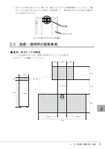
Page 67: ...4 ラック設置後の取り扱いについて 67 J 図は 1U 2U 3U 用をまとめて表示していますが 実際の取り付けは空きスペー スに応じて 適切なサイズを選択し 取り付けてください ...

Page 68: ...68 ...

Page 69: ...pt in an easy to access location for quick reference when using this product High Safety The Products are designed developed and manufactured as contemplated or general use including without limitation general office use personal use household use and ordinary industrial use but are not designed developed and manufactured as contemplated for use accompanying fatal risks or dangers that unless extr...

Page 70: ...gency of the WARNING and CAUTION Details are described next to the triangle A barred circle warns against certain actions Do Not Details are described next to the circle A black circle indicates actions that must be taken Details are described next to the black circle Symbols Meaning These sections explain prohibited actions and points to note when using this product Make sure to read these sectio...

Page 71: ...tion and Installation 80 3 1 Configuration 80 3 2 Opening the Front Door 82 3 3 Opening the Rear Door 83 3 4 Installing the Rack 84 3 5 Connecting Racks 86 4 Handling the Rack after Installation 93 4 1 Cage nut Insertion and Removal Procedures 93 4 2 Changing the Position of the Door Rotation Axis 97 4 3 Mounting a General purpose Table Fixed Type 115 4 4 Mounting a General purpose Table Movable T...

Page 72: ...Two versions of the 19 inch rack Model 1740 are shown below 1 1 Specifications The rack specifications are listed below Model 1740 Unit mounting capacity 40U Type name With stabilizer Without stabilizer Base rack 19R 174A1 Expansion rack 19R 174B1 Base rack 19R 174A2 Expansion rack 19R 174B2 Size w x d x h mm 700 x 1272 x 2000 700 x 1050 x 2000 Model 1740 19R 174A1 19R 174A2 ...

Page 73: ...ther you will need to use stabilizers on your 19 inch rack will depend on the rack installation method that you follow Devices mounted in the rack center Although devices are mounted toward the right side on conventional standard and global racks when viewed from the front on the 19 inch rack they are mounted in the center This ensures that cables do not become concentrated on one side of the rack...

Page 74: ...out 1 000 kg Secure a sufficient installation area to ensure normal operation and maintenance of the rack system To reduce the risk of failure fire or electric shock do not place metallic objects or containers bearing water such as vases flowerpots or drinking glasses on or near the rack Avoid placing the rack in locations exposed to oil vapors or excessive humidity or dust or with poor ventilatio...

Page 75: ...the rack push the lower part of the rack rather than the middle of the rack to keep the rack from falling over The barycentric position of the rack can be higher than the center of the rack depending on where individual devices are installed Also do not push on the rack sides Doing so may cause the rack to fall over Pushing against the center of the front door or the air vent opening may cause the...

Page 76: ...cautions for Installation and Operation Securing adequate clearance for ventilation and maintenance When installing the rack secure adequate clearance for ventilation and maintenance as shown below Key is here K ey closes Bag with key ins Front door When the key is attached to the rack Clearance for ventilation and maintenance Front view of the rack Top view of the rack Front of the rack 700mm 200...

Page 77: ... with the leveling feet that are provided on the bottom of the rack Adjust the leveling feet so that the rack is level Keep the casters 1 to 2 mm above the floor Use bolts to secure the rack to the floor slab Failure to use bolts to secure the rack to the floor slab may cause the rack to fall over during any earthquake with a seismic intensity exceeding 250 Gal If the rack falls over the result ma...

Page 78: ... Mounting Procedure When installing a rack that comes with stabilizers be sure to attach the stabilizers If not the rack may tip over when a device is drawn out from the rack When installing a rack that comes with no stabilizers be sure to anchor the rack to a stabilizing surface The rack may tip over if it is not anchored to a stabilizing surface If the blank panel is not mounted the exhaust will...

Page 79: ... they fall over If the doors need to be removed contact a Fujitsu Limited maintenance engineer Contact a Fujitsu Limited maintenance engineer before attempting to move the rack after installing it Transporting or moving the rack without taking the proper procedures and precautions may result in damage to the rack To prevent the rack from becoming unstable do not climb on it or lean against it ...

Page 80: ...700 x 1272 including stabilizers rack unit 1050 x 2000 Load capacity kg Total rack capacity 943 kg 1 Total load capacity 800 kg excluding rack Rack 143 kg including stabilizers Total rack capacity 910 kg 1 Total load capacity 800 kg excluding rack Rack 110 kg including stabilizers Security Front and rear doors locked with keys Key operation is required to lock handle Accessories Front door rear do...

Page 81: ...kg 1 Total load capacity 800 kg excluding rack Rack 135 kg Total rack capacity 902 kg 1 Total load capacity 800 kg excluding rack Rack 102 kg Security Front and rear doors locked with keys Key operation is required for handle locking Accessories Front door rear door and a pair of side covers attached to the rack before shipment Rack door keys 2 Cage nuts screws washers attached before shipment 50 ...

Page 82: ...the key for the rack From the front of the door lift and pull the rack handle CAUTION Close the front door after fully securing the installed devices Failure to do so may cause the devices to fall off the rack and be damaged in the event of an earthquake ...

Page 83: ...3 Rack Configuration and Installation 83 E 3 3 Opening the Rear Door 1 Unlock the door with the key for the rack From the front of the door lift and pull the rack handle ...

Page 84: ...et or a Quake Proof Stabilizer Kit 3 4 1 Installing a rack supplied with a stabilizer The rack is supplied with a stabilizer as standard which is attached on the front of the rack Attach the stabilizer as shown in the figure below WARNING Always use the stabilizers when installing the rack Failure to do so may cause the rack to tip over when a device in the rack is pulled out Securing the stabiliz...

Page 85: ...ttaching the Quake Proof Stabilizer kit is shown below 1 Attach the kit stabilizers to the front rear and right left sides of the rack The Quake Proof Stabilizer kit is an optional product 2 Attach the stabilizers to the rack using three bolts for the front and right left sides and two bolts for the rear 3 Anchor the kit stabilizers to the floor 1 Anchor the stabilizers on the front rear sides to ...

Page 86: ...epladder because some of the work will need to be performed at height To prevent equipment damage and electric shock turn off the power to the server and peripherals and disconnect the power cables from the outlet before connecting racks To prevent injury ensure that at least two persons perform the rack connection work You may get on a stepladder when working on the upper part of the rack Be care...

Page 87: ...ow example connecting an expansion rack to the right of the base rack 1 Removing the side cover of the existing rack Remove the eight M6 screws securing the side cover and then remove the side cover Be careful not to lose the M6 screws removed here They will be used later Side cover M6 screw ...

Page 88: ...tion side Also remove the screws or bolts from the front rear Quake Proof Stabilizer kit components that are on the side to which another rack will be connected Be careful not to lose the Quake Proof Stabilizer kit components and bolts They will be used later Bolt that secures the stabilizer to the floor Quake Proof Stabilizer kit component rear Bolt on the rack connection side Bolt that secures t...

Page 89: ...tion side in order from the top of the rack Attach the shield rubber to the front and rear frames of the rack 4 Align the height of the expansion rack with that of the existing rack Line up the side of the expansion rack with the side of the existing rack and then adjust the expansion rack feet to align the expansion rack height with that of the existing rack ࡈ ࡓ Shield rubber Frame ...

Page 90: ...those removed from the existing rack At this stage tighten the bolts only temporarily They will need to be tightened firmly after the mounting fixtures are attached The front and rear Quake Proof Stabilizer kit components each have three bolt holes On each side the bolt for the one closest to the existing rack will be tightened together with the mounting fixture later So leave that bolt unapplied ...

Page 91: ... lower front and one on the lower rear of the rack each with two M8 bolts Use the M8 bolts used for the Quake Proof Stabilizer kit If you are not using the Quake Proof Stabilizer kit use the bolts that come with the connection kit Note When the Quake Proof Stabilizer kit components are attached some of the M8 bolts of the Quake Proof Stabilizer kit will not be required and therefore some of the bo...

Page 92: ...er on the expansion rack Lastly mount the side cover which was removed from the existing rack with the M6 screws which were also removed from the existing rack This completes the rack connection procedure Side cover M6 screw ...

Page 93: ... cage nut from the inside of the rack Insert one edge of the cage nut into the cage nut hole of the rack The following figure shows the case where the edge of the cage nut is inserted into the lower hole 2 From the outside of the rack insert the tip of the cage nut tool into the hole that has the installed cage nut and snap the other edge of the cage nut into the hole Direction of edge of the cage...

Page 94: ...l or standard screwdriver is completely inserted between the edge of the cage and the mounting flange If the tip is inserted incompletely the edge of the tool or standard screwdriver may slip off leading to potential injury Secure the cage nut such as with adhesive tape to prevent it from falling into the rack When holding the cage nut between your fingertips be sure to grasp its left and right si...

Page 95: ...the system is expanded or relocated in the future Procedure using a standard screwdriver CAUTION Be sure not to place any finger anywhere past the points indicated Otherwise the finger may strike the rack when you push on the cage which may lead to injury Secure the cage nut such as with adhesive tape to prevent it from falling into the rack When holding the cage nut between your fingertips be sur...

Page 96: ...96 1 Insert the tip of a standard screwdriver between the edge of the cage and the mounting flange and then press the edge of the cage 2 Push down on the standard screwdriver to remove the cage nut ...

Page 97: ... during the removal and reinstallation of parts Removed parts are all reused No excess parts should be left over Note that the rack is supplied with no spare parts Removing and installing some parts will require certain degrees of strength Work carefully General tools such as Phillips screwdrivers No 2 bit standard screwdrivers etc are required for the following operations 4 2 1 Changing the posit...

Page 98: ...be used later Keep them in a safe and convenient location Lift up the entire door to remove the door Be careful not to get your fingers caught in the gap between the door and the rack M5 hexagon head screws Stopper wire Hinge set Screw securing the lower hinge two locations upper and lower Lower hinge ...

Page 99: ...wer hinge assemblies The hinge spacer attached to each hinge assembly is removed together with it Remove the M5 flat head screws to remove rod receiving brackets upper center and lower Hinge spacer M5 screw Hinge assembly Two locations upper and lower Rod receiving bracke M5 flat head screws three screws upper center and lower ...

Page 100: ... screws Each screw is a self tapping screw which requires a certain degree of strength to tighten Confirm that the hinge assemblies and rod receiving brackets are installed correctly as shown in Normal state after installation Hinge assembly Two locations upper and lower M5 screw Rod receiving bracket Side cover Side cover M5 flat head screw Three locations upper center lower Normal state after in...

Page 101: ... may fall on you Work carefully Remove the upper and lower M5 screws securing the door handle Remove the door handle together with the rods from the door Remove the M4 screw to remove the Fujitsu logo Place your hand on the Fujitsu logo while removing the M4 screw to prevent the Fujitsu logo from falling Rod Fujitsu logo Standard screwdriver Rod supporter two locations upper and lower M4 screw Doo...

Page 102: ... not to lose the spacer While holding the upper short rod with the curved end facing the left secure the rod together with the spacer to the right side of the handle with the M3 bind head screw The upper and lower rods are different in length The upper rod is shorter than the lower rod Upper rod short Upper rod short Disassemble Assemble M3 bind head screw Spacer Lower rod long Lower rod long ...

Page 103: ...and rods from the front of the door in such a way that the upper short rod will be on top Secure the door handle with the M5 screws Secure the upper and lower rods with the rod supporters Door handle Door Upper rod short Lower rod long Rod Rod supporter Normal state after installation Upper and lower supporters M5 screw Door handle ...

Page 104: ...ttach the Fujitsu logo Secure the Fujitsu logo using an M4 screw from the rear of the door The standard location for the logo is 103 mm from the left side and 122 mm from the top M4 screw Fujitsu logo 122 103 ...

Page 105: ...Fully tighten the screw while taking care not to tilt the hinge Tighten the retaining screws for the upper hinge set component while pressing down on it in the direction of the lower hinge set component Loosen the retaining screws of the lower hinge set component and then lower the component as far as it will go The retaining screws of the lower hinge set component will be fully tightened after th...

Page 106: ... assembly and upper hinge set component is the same as that between the hinge assembly and lower hinge set component If they are different adjust the lower hinge set component or hinge assembly mounting position Secure the stopper wire to the frame with an M5 hexagon head screw and fully tighten the screw for the door wire that was temporarily tightened Tighten the screws to secure the stopper wir...

Page 107: ...ips screwdriver to loosen the screws Just loosen the screws You do not need to remove them 2 Remove the M5 hexagon head screws and then remove the stopper wire The removed screws and wire will be used later Keep them in a safe and convenient location Lift up the entire door to remove the door Be careful not to get your fingers caught in the gap between the door and rack Stopper wire M5 hexagon hea...

Page 108: ...he hinge spacer attached to each hinge assembly is removed together with it Remove the M5 flat head screws to remove the rod receiving brackets upper center and lower Hinge spacer M5 screw Hinge assembly Two locations upper and lower Rod receiving bracket M5 flat head screws Three screws upper center and lower ...

Page 109: ...brackets with M5 flat head screws Each screw is a self tapping screw which requires a certain degree of strength to tighten Confirm that the hinge assemblies and rod receiving brackets are installed correctly as shown in Normal state after installation Hinge assembly M5 screw Two locations upper and lower Rod receiving bracket M5 flat head screw Three locations upper center lower Normal state afte...

Page 110: ...ower rod supporters and then remove all supporters The upper rod may fall on you Work carefully Remove the upper and lower M5 screws securing the door handle Remove the door handle together with the rods from the door Rod Door handle Rod supporter Standard screwdriver two locations upper and lower M5 screw Door Door handle Rod ...

Page 111: ...ether with it Be careful not to lose the spacer While holding the upper short rod with the curved end facing the left use the M3 bind head screw and the spacer to secure the rod to the right side of the handle The upper and lower rods are different in length The upper rod is shorter than the lower rod Upper rod short Upper rod short Lower rod long Spacer M3 bind head screw Lower rod long Disassemb...

Page 112: ...component positions Attach the stopper wire to the door and temporarily tighten the M5 hexagon head screw This screw will be fully tightened when the wire is attached to the rack Adjust the hinge positions The upper hinge set component has been left loose since the door was removed Lower the upper hinge set component as far as it will go and then tighten the retaining screw Fully tighten the screw...

Page 113: ...omponent and then lower the component as far as it will go The retaining screws of the lower hinge set component will be fully tightened after the door is mounted on the rack For now tighten it only temporarily M5 hexagon head screw Hinge retaining screw Lower hinge set component Upper hinge set component view from the front of the door Stopper wire Full tightening View from the rear of the door H...

Page 114: ...he gap between the hinge assembly and upper hinge set component is the same as that between the hinge assembly and lower hinge set component If they are different adjust the lower hinge set component or hinge assembly mounting position Secure the stopper wire to the frame with an M5 hexagon head screw and fully tighten the screw for the door wire that was temporarily tightened Tighten the screws t...

Page 115: ...e information on the mounting procedure see Section 4 1 1 Insertion 1 Open the front door and insert the M6 cage nuts into the front post of the rack Insert cage nuts into two upper and lower square holes out of three between the location lines The mounting locations are as follows one nut in each of the upper and lower square holes among the three square holes height of 1U at the location line ma...

Page 116: ...he rack The mounting locations are as follows one nut in each of the upper and lower square holes among the three square holes height of 1U at the location line marking the mounting location of the table Two nuts on each of the left and right sides make up a total of four nuts ...

Page 117: ... according to Section 4 3 1 Inserting cage nuts temporarily fix the rear brackets R and L to the rack post Use M6 screws to fix the brackets in position In step 2 you will mount the table on rear brackets L and R Temporarily fix the rear brackets in position to the extent that the table will not drop down when it is placed on the rear brackets Carefully follow the installation directions for rear ...

Page 118: ... attached in step 2 according to Section 4 3 1 Inserting cage nuts Place the rear of the table on rear brackets L and R that were attached in step 1 3 Confirm that the heights of the left and right square holes into which the hooks were inserted are the same Since the table is only provisionally mounted refrain from placing any loads on it ...

Page 119: ... position Start work after confirming that rear brackets L and R will not fall down when the table is placed on them When mounting the table provisionally ensure that the table is securely mounted with the front hook fully inserted in the relevant square hole Also ensure that the rear part of the table is securely mounted on rear brackets L and R Do not take away the supporting hand until the tabl...

Page 120: ...inst the table so that no gaps appear in the directions of arrows B and C If you are unable to press against rear brackets L and R adequately do so after slightly loosening the M6 screws marked with an asterisk Rack post A B C A C B G G The same screw hole positions on rear bracket L Section G G Screw holes of rear bracket R used to secure the table in position Table Rear bracket R First screw hol...

Page 121: ...kets L and R which were temporarily fixed in position in step 1 according to Section 4 3 2 Attaching rear brackets and temporarily mounting the table to the rack posts 4 Confirm that all M6 screws and M6 bolts have been tightened Confirm that the table does not occupy the U space under the table ...

Page 122: ...122 5 Make readjustments as required by loosening the M6 screws that secure the table to the rack posts ...

Page 123: ... for mounting a general purpose table fixed type is as follows 1 Insert cage nuts 2 Attach rear brackets 3 Mount the table 4 4 1 Inserting cage nuts Insert the M5 and M6 cage nuts into the rack posts front and rear For more information on the mounting procedure see Section 4 1 1 Insertion General purpose Table Movable Type Type name 19R 16TR2 Component name Quantity Table 1 Rear bracket L 1 Rear b...

Page 124: ...U at the location line marking the mounting location of the table One nut on each of the left and right sides makes up a total of two nuts Insert the M6 cage nuts into the upper and lower square holes among the three square holes height of 1U at the location line marking the mounting location of the table Two nuts on each of the left and right sides make up a total of four nuts ...

Page 125: ...e rack Insert M6 cage nuts into two upper and lower square holes out of three between location lines on the rack post Two nuts on each of the left and right sides make up a total of four nuts Align the heights of all attached M6 cage nuts Attach the M5 cage nuts to only the front posts of the rack not to the rear posts ...

Page 126: ...osition adjustment bracket and rear bracket R to the rack post Use M6 screws to fix the brackets in position In step 2 you will mount the table on rear brackets L and R Temporarily fix the rear brackets in position to the extent that the table will not drop down when it is placed on the rear brackets 2 Confirm that front brackets L and R being held in position by the simple retainer mechanism of t...

Page 127: ...ght above the M6 cage nuts that were attached in step 2 according to Section 4 4 1 Inserting cage nuts Place the rear of the table on rear brackets L and R that were attached in step 1 4 Confirm that the heights of the left and right square holes into which the hooks were inserted are the same Since the table is only provisionally mounted refrain from placing any loads on it ...

Page 128: ... move The slide rails and front brackets L and R are assembled with the table before shipment Start work after confirming that rear brackets L and R will not fall down when the table is placed on them When mounting the table provisionally ensure that the table is securely mounted with the front hook fully inserted in the relevant square hole Also ensure that the rear part of the table is securely ...

Page 129: ... out about 185 mm until the screw holes for securing rear brackets L and R are visible Do not draw it out too much see section G G When mounting the table on a 19 inch rack other than the SE RxRCxx MC RxRCxx and PW RxRCxx use screw holes for which the spacing of the M6 screws used to secure rear brackets L and R to front brackets L and R is maximized 4 Put away the table that was drawn out in step...

Page 130: ...mporarily fixed in position in step 1 according to Section 4 4 2 Attaching rear brackets to the rack posts 6 Confirm that all M6 screws have been tightened Tighten the panel fastener to secure the table in position Confirm that the table does not occupy the U space under the table ...

Page 131: ...4 Handling the Rack after Installation 131 E 7 Make readjustments as required by loosening the M6 screws that secure the table to the rack posts ...

Page 132: ...nents Confirm that all components have been delivered see the table below Also prepare the necessary tools Phillips screwdriver No 2 bit Product name Type name Component and quantity Cable holder front 19R 17CM1 Cable holder front x 1 M5 screw x 1 Cable holder rear 19R 17CM2 Cable holder rear x 1 M5 screw x 1 ...

Page 133: ... is supplied with the rack Use a Phillips screwdriver to tighten the M5 screw The screw is a self tapping screw which needs to cut its own threads as it is screwed into its hole For this reason tightening the screw requires a certain degree of strength Frame Front M5 screw Phillips screwdriver Front cable holder Frame M5 screw Phillips screwdriver Rear Rear cable holder ...

Page 134: ... each at 1U and 2U four in total on left and right 3U One center hole each at 1U and 3U four in total on left and right 2 Secure the blank panel with M6 screws Secure the blank panels with screws through the holes corresponding to the cage nuts attached in step 1 The figure shows a general representation of 1U 2U and 3U blank panels In actual work select and mount the appropriate size of blank pan...

Page 135: ...rights arising from the use of any information in this manual No part of this manual may be reproduced in any form without the prior written permission of Fujitsu Any manual which has missing pages or which is incorrectly collated will be replaced 19 インチラック モデル 1740 取扱説明書 19 inch rack Model 1740 User s Guide 19R 174A1 19R 174B1 19R 174A2 19R 174B2 C120 E557 01XA 発 行 日 発行責任 2008 年 12 月 富士通株式会社 Issu...

Page 136: ...このマニュアルは再生紙を使用し リサイ クルに配慮し て製本されています 不要になった際は 回収 リサイ クルに出し て く だ さい CoverEnd fm 2 ページ 2009年1月8日 木曜日 午後11時45分 ...

Reviews: