


112
7
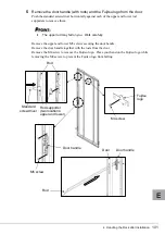
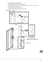
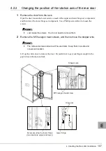
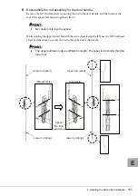
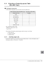
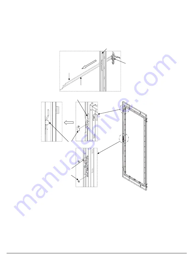
Install the door handle and rods.
Before starting this work, turn the door upside down.
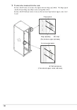
Insert the assembly of the door handle and rods from the front of the door in such a way that
the upper (short) rod will be on top.
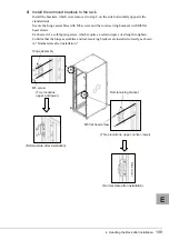
Secure the door handle with the M5 screws.
Secure the upper and lower rods with the rod supporters.
’
8
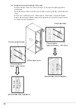
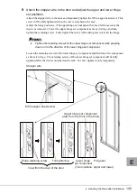
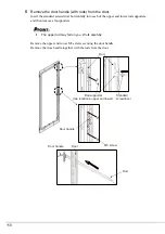
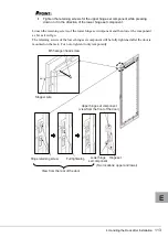
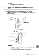
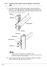
Attach the stopper wire to the door and adjust the upper and lower hinge
set component positions.
Attach the stopper wire to the door and temporarily tighten the M5 hexagon head screw. This
screw will be fully tightened when the wire is attached to the rack.
Adjust the hinge positions. (The upper hinge set component has been left loose since the
door was removed.) Lower the upper hinge set component as far as it will go and then
tighten the retaining screw. Fully tighten the screw while taking care not to tilt the hinge.
Door
Lower rod (long)
Door handle
Upper rod (short)
Upper rod (short)
(Normal state
after installation)
Rod supporter
(Upper and lower supporters)
Door handle
M5 screw
Summary of Contents for 1740
Page 1: ...J E ...
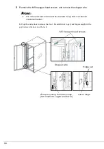
Page 15: ...3 ラックの構成と設置 15 J 3 3 リヤドアの開き方 1 扉用キーを回し ラックハンドルを持ち上げ 手前に引きます ...
Page 28: ...28 1 マイナスドライバの先端をケージナットの爪とラック柱の間に挿入して ケージナットの爪に押し込みます 2 マイナスドライバを押し下げて取り外します ...
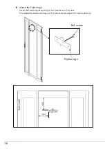
Page 36: ...36 8 富士通ロゴを取り付けます 富士通ロゴを扉の裏から M4 ネジで固定します 標準的な取り付け位置は 横方向寸法が 103 縦方向寸法が 122 です ࡀࠫ ን ㅢࡠࠧ ...
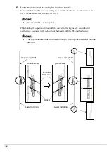
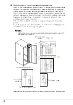
Page 54: ...54 5 必要に応じてラックの柱に固定している M6 ネジを緩め 再調整をしてく ださい ...
Page 63: ...4 ラック設置後の取り扱いについて 63 J 7 必要に応じてラックの柱に固定している M6 ネジを緩め 再調整をしてく ださい ...
Page 67: ...4 ラック設置後の取り扱いについて 67 J 図は 1U 2U 3U 用をまとめて表示していますが 実際の取り付けは空きスペー スに応じて 適切なサイズを選択し 取り付けてください ...
Page 68: ...68 ...


