


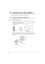


122
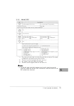
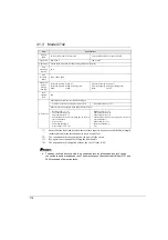
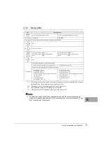
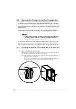
3.5
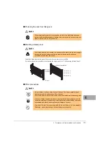
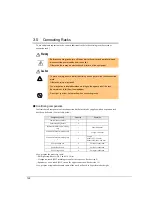
Connecting Racks
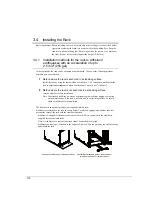
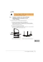
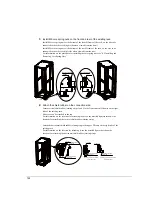
To use additional expansion racks, connect additional racks to the existing rack (base rack or
expansion rack ).
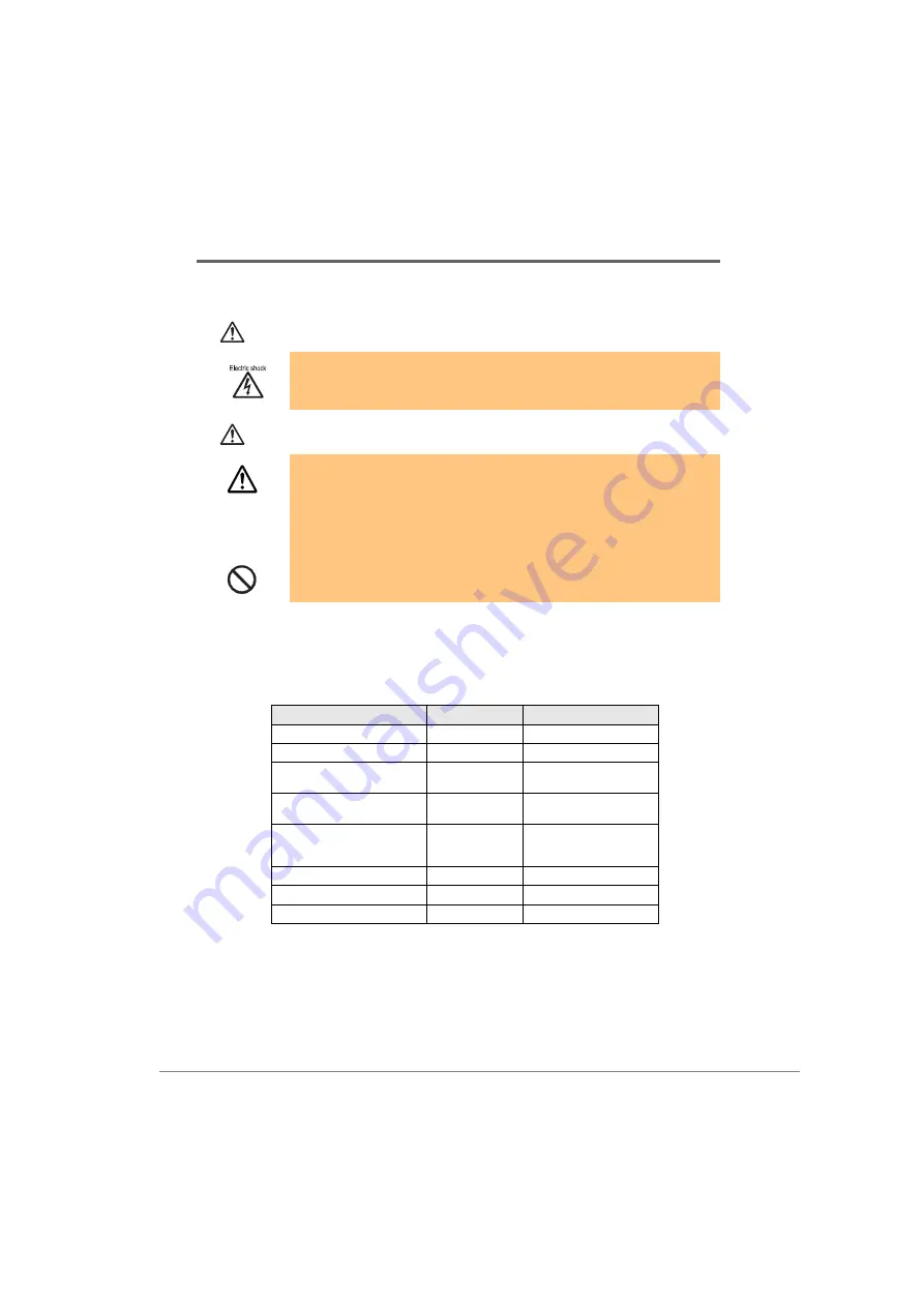
Warning
Caution
■
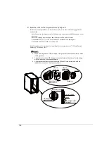
Confirming components
Confirm that all components of the connection kit that need to be supplied with an expansion rack
have been delivered (see the table below).
Also, prepare the necessary tools:
・
Phillips screwdrivers (No. 2 and No. 3 bits)
・
Hexagon wrench (M12 retaining screws for the top cover: Socket size 8)
・
Spanner or box wrench (M12 screws for upper connection: Socket size 19)
Also, prepare a stepladder because some of the work will need to be performed at height.
・
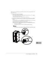
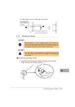
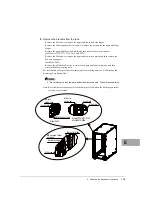
Before connecting racks, turn off the power to the server and peripherals and
disconnect the power cables from the outlet.
Otherwise, there may be electric shock or failure of the equipment.
・
To prevent injury, ensure that at least two persons perform the rack connection
work.
Otherwise, injury may result.
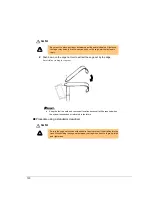
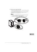
・
You may get on a stepladder when working on the upper part of the rack.
Be careful not to fall from the stepladder.
・
Do not put your foot on the racks when connecting racks.
Component name
Quantity
Remarks
Lower mounting fixture
2
Upper mounting fixture
2
Horizontal shield rubber jointing
strip
1
Length: 880 mm
Vertical shield rubber jointing strip
1
2
Length: 1,000 mm
Vertical shield rubber jointing strip
2
2
Length
Model 2737: 650 mm
Model 2742/2642: 860 mm
M6 core spring nut
8
For lower connection
M6 flat head screw
8
For lower connection
M12 hexagon bolt
4
For upper connection
Summary of Contents for 19R-261A2
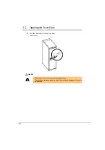
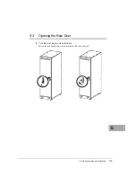
Page 20: ...20 3 3 後扉の開き方 1 扉用キーを回し解除します ラックハンドルを手前に引き上げ 矢印の方向にハンドルを回転し 手前に引きま す ...
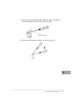
Page 32: ...32 1 マイナスドライバの先端をケージナットの爪とラック柱の間に挿入して ケージナットの爪に押し込みます 2 マイナスドライバを押し下げて取り外します ...
Page 72: ...72 5 0 5 0 ࡢሙྜ ࢣ ࣈࣝ ࣝࢲ 0 ࢥ ࣛࢵࢺ 0 ࢧࣛࢿࢪ 5 0 5 0 ࡢሙྜ ࢣ ࣈࣝ ࣝࢲ 0 ࢥ ࣛࢵࢺ 0 ࢧࣛࢿࢪ ...
Page 73: ...4 ラック設置後の取り扱いについて 73 J 5 0 5 0 ࡢሙྜ ࢣ ࣈࣝ ࣝࢲ 0 ࢥ ࣛࢵࢺ 0 ࢧࣛࢿࢪ 5 0 5 0 ࡢሙྜ ࢣ ࣈࣝ ࣝࢲ 0 ࢥ ࣛࢵࢺ 0 ࢧࣛࢿࢪ ...
Page 84: ...84 3 背面より M5 サラネジで取り付けプレートとラック およびスタビライ ザー本体を固定します 4 前面の M5 サラネジを本締めします 0 ࢧࣛࢿࢪ ྲྀ ࡅࣉࣞ ࢺ 㠃ഃ ...
Page 88: ...88 ...
Page 92: ...92 ...
Page 100: ......
Page 186: ......
Page 188: ......


