


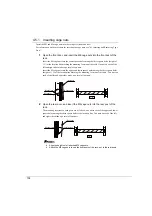
4
Handling the Rack after Installation
143
E
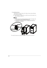
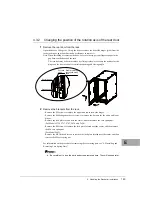
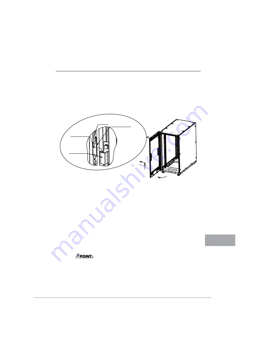
4.3.2
Changing the position of the rotation axis of the rear door
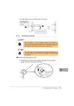
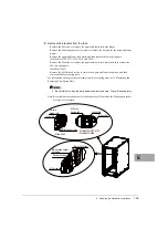
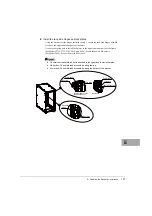
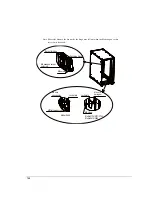
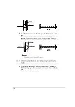
1
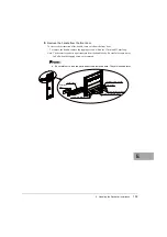
Remove the rear door from the rack.
Open the door by 90 degrees. Lift up the door to remove the door-side hinges (pins) from the
rack-side hinges, and then slide the door sideways to remove it.
Note: When installing or removing the door, be careful not to get your fingers caught in the
gap between the door and the rack.
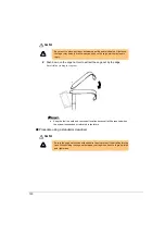
The rear door may be hard to remove by sliding it sideways because the notches for the
hinges on the door are bent to control the opening and closing angle.
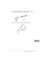
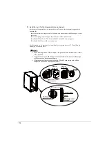
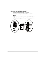
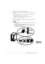
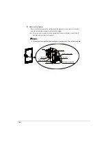
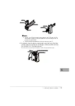
2
Remove the brackets from the rack.
・
Remove the M6 screws to remove the upper and lower rack-side hinges.
・
Remove the M6 hexagon socket set screws to remove the bar nuts for the upper and lower
hinges.
・
Remove the lock plate located near the center, and then remove the core spring nut.
(For Models 2724, 2737, 2742, 2616, and 2624):
Remove the M6 screws to remove the lock plate located near the center, and then remove
the M6 core spring nut.
(For Model 2642):
Remove the M5 flat head screws to remove the lock plate located near the center, and then
remove the M5 core spring nut.
For information on the procedure for removing the core spring nuts, see "4.2 Installing and
Removing Core Spring Nuts".
Be careful not to lose the parts and screws removed here. They will be used later.
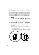
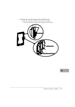
Door-side
hinge
Bend for controlling
opening and closing
angle
Rack-side hinge
Notch for hinge
Summary of Contents for 19R-261A2
Page 20: ...20 3 3 後扉の開き方 1 扉用キーを回し解除します ラックハンドルを手前に引き上げ 矢印の方向にハンドルを回転し 手前に引きま す ...
Page 32: ...32 1 マイナスドライバの先端をケージナットの爪とラック柱の間に挿入して ケージナットの爪に押し込みます 2 マイナスドライバを押し下げて取り外します ...
Page 72: ...72 5 0 5 0 ࡢሙྜ ࢣ ࣈࣝ ࣝࢲ 0 ࢥ ࣛࢵࢺ 0 ࢧࣛࢿࢪ 5 0 5 0 ࡢሙྜ ࢣ ࣈࣝ ࣝࢲ 0 ࢥ ࣛࢵࢺ 0 ࢧࣛࢿࢪ ...
Page 73: ...4 ラック設置後の取り扱いについて 73 J 5 0 5 0 ࡢሙྜ ࢣ ࣈࣝ ࣝࢲ 0 ࢥ ࣛࢵࢺ 0 ࢧࣛࢿࢪ 5 0 5 0 ࡢሙྜ ࢣ ࣈࣝ ࣝࢲ 0 ࢥ ࣛࢵࢺ 0 ࢧࣛࢿࢪ ...
Page 84: ...84 3 背面より M5 サラネジで取り付けプレートとラック およびスタビライ ザー本体を固定します 4 前面の M5 サラネジを本締めします 0 ࢧࣛࢿࢪ ྲྀ ࡅࣉࣞ ࢺ 㠃ഃ ...
Page 88: ...88 ...
Page 92: ...92 ...
Page 100: ......
Page 186: ......
Page 188: ......


