background image

COPYRIGHT

Fu j i t su

PC Corpora ti on has made every e

ff

ort to 

en su re the acc u racy and com p l eteness of this doc u m en t .
However, as on going devel opm ent e

ff

orts are con ti n -

u a lly improving the capabi l i ties of our produ ct s , we 
cannot guara n tee the acc u racy of the con tents of t h i s
doc u m en t . We disclaim liabi l i ty for errors , om i s s i on s ,
or futu re ch a n ge s .

LifeBook, Fujitsu,and the Fujitsu logo are trademarks
of Fujitsu Limited.
The fo ll owing are regi s tered tradem a rks of
IBM Corpora ti on :I B M , IBM PC AT, IBM PS/2.
The fo ll owing are regi s tered tradem a rks of
Mi c ro s oft Corpora ti on :M S ,M S - DO S , Wi n dows 95.
PCMCIA is a tradem a rk of the Pers onal Com p uter
Mem ory Ca rd In tern a ti onal As s oc i a ti on .
P h oenix and the Phoenix logo are regi s tered 
tradem a rks of P h oenix Tech n o l ogi e s ,L td .
Pentium is a registered trademark and 
MMX technology is a trademark of Intel Corporation.
P C - Doctor is a tradem a rk of w a ter ga te . s of t w a re . i n c .
Sof t PEG is a regi s tered tradem a rk of

Com p u Core Mu l ti m edia In c .
LapLink is a regi s tered tradem a rk of
Traveling Sof t w a re In c .
Au d i o Rack is a regi s tered tradem a rk of
ESS Tech n o l ogy, In c .
Mega P h one is a regi s tered tradem a rk of
Cypress Re s e a rch Corpora ti on

All other tradem a rks men ti on ed herein are the 
property of t h eir re s pective own ers .

We cannot guara n tee the acc u racy of the con tents of
this doc u m en t . We disclaim liabi l i ty for errors ,
om i s s i on s , or futu re ch a n ge s .

© Copyri ght 1996 Fu j i t su PC Corpora ti on . All ri gh t s
re s erved . No part of this publ i c a ti on may be cop i ed ,
reprodu ced , or tra n s l a ted , wi t h o ut pri or wri t ten 
con s ent of Fu j i t su PC Corpora ti on . No part of t h i s
p u bl i c a ti on may be stored or tra n s m i t ted in any 
el ectronic form wi t h o ut the wri t ten con s ent of
Fu j i t su PC Corpora ti on .

D E C LA RATION OF CONFORMITY

according to FCC Part 15

Responsible Party Name: Fujitsu PC Corporation

Address: 598 Gibraltar Drive

Milpitas,CA 95035

Telephone: (408) 935-8800

Declares that product: Model:LifeBook 735Dx.

LifeBook 755Tx.
LifeBook 765Tx.

Complies with Part 15 
of the FCC Rules.

This  devi ce complies with  Pa rt  15  of the FCC ru l e s .
Opera ti ons is su bj ect to the fo ll owing two con d i ti on s :
(1) This devi ce must not be all owed to cause harm f u l
i n terferen ce , (2) This devi ce must accept any interfer-
en ce  received , i n cluding  interferen ce  that  may  cause
u n de s i red opera ti on .

D avid Woo

Fu j i t su

9 / 2 3 / 9 7

   

    

 

Summary of Contents for 735Dx

Page 1: ... a registered trademark of ESS Technology Inc MegaPhone is a registered trademark of Cypress Research Corporation All other trademarks mentioned herein are the property of their respective owners We cannot guarantee the accuracy of the contents of this document We disclaim liability for errors omissions or future changes Copyright 1996 Fujitsu PC Corporation All rights reserved No part of this pub...

Page 2: ...Ns contact your local telephone company If this equipment causes harm to the telephone net work your telephone company may discontinue your service temporarily If possible they will notify you in advance If advance notice is not practical they will notify you as soon as possible You will also be advised of your right to file a complaint with the FCC This fax modem also complies with fax branding r...

Page 3: ...ique de la class B respecte toutes les exigence du Réglement sur le matérial brouilleur du Canada Notice to Users of the Canadian Telephone Network The Canadian Industry Canada label identifies certi fied equipment This certification means that the equipment meets certain telecommunications net work protective operational and safety requirements The Department does not guarantee the equipment will...

Page 4: ...ées par un service de maintenance agréé au Canada Toute réparation ou modification qui n est pas expressément approuvée par Fujitsu PC Corp C A U T I O N For safety users should ensure that the electrical ground of the power utility the telephone lines and the metallic water pipes are connected together Users should NOT attempt to make such connections themselves but should contact the appropriate...

Page 5: ... WARNING CMOS and NiCAD batteries may explode if mistreated Do not recharge disassemble or dispose of in fire A V E R T I S S E M E N T Pour assurer la sécurité les utilisateurs doivent vérifier que la prise de terre du service d électricité les lignes téléphoniques et les conduites d eau métalliques sont connectées ensemble Les utilisateurs NE doivent PAS tenter d établir ces connexions eux mêmes...

Page 6: ...T a b l e o f C o n t e n t s ...

Page 7: ...s Indicator Panel 19 Power On 23 Power Off 24 Restarting the System 25 Fujitsu Welcome Center 26 Batteries 26 Integrated ErgoTrac Pointing Device 30 Using the Keyboard 32 Volume Control 34 Floppy Disk Drive 34 CD ROM Drive 36 Hard Drive 38 Power Management 38 Internal Modem 46 Infrared Port 46 Pre Installed Software 47 SECTION THREE CONFIGURING YOUR LIFEBOOK 700 SERIES Boot Sequence 52 Identifying...

Page 8: ...ry Upgrade Module 108 Landock 111 Port Replicator 112 SECTION FIVE TROUBLESHOOTING Identifying the Problem 118 Specific Problems 119 Power On Self Test Messages 138 Emergency CD ROM Tray Release 141 Modem Setup and Commands 141 Restoring Your Pre installed Software from CD ROM 141 SECTION SIX CARE AND MAINTENANCE Care and Maintenance 144 Caring for Your Notebook 144 Increasing Battery Life 145 Car...

Page 9: ...LifeB o ok 70 0 Series f rom Fu jit su P r e f a c e ...

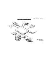
Page 10: ... It has a powerful interface that enables it to support a variety of optional features Figure P 1 CONVENTIONS USED IN THE GUIDE Screen examples in this manual are intended as examples only and screen and file names may differ in actual use Messages displayed by the LifeBook 700 Series appear in Courier type Example Shutdown the computer Keyboard keys are shown in boldface Helvetica type Example Fn...

Page 11: ...L i f e B o o k 7 0 0 S e r i e s f r o m F u j i t s u L if e B o ok 7 0 0 S e r ie s f r om F uj i t su vii Figure P 1 LifeBook 700 Series with Both Fujitsu and Third Party Options ...

Page 12: ...nent Identification 4 Top and Front Components 6 Left Side Panel Components 7 Right Side Panel Components 7 Rear Panel Components 8 Bottom Components 10 Power Sources 10 Data Security 11 Starting Your Notebook for the First Time 12 User Registration 14 Learning About Your Operating System and Application Software 15 ...

Page 13: ...ed in the accessories box Figure 1 2 Modular Lithium ion battery already installed in Multi function Bay 1 of your notebook Modular 20 speed maximum CD ROM drive already installed in Multi function Bay 2 of your notebook Modular 3 5 floppy disk drive located in the accessories box Figure 1 4 Device adapter for Multi function Bay 2 located in the accessories box Figure 1 3 RJ 11 cable located in th...

Page 14: ... with MMX technology 16MB or 32MB SDRAM standard expand able to 80MB or 96MB 12 1 dual scan DSTN or active matrix TFT color display with 800 x 600 resolution 2MB EDO video RAM Built in 1 6GB 2GB or 3 2GB hard drive Dual Multi function bays which support the following 3 5 floppy disk drive included with all models 20 speed maximum CD ROM drive included with all models for Bay 2 only Optional second...

Page 15: ... size keyboard with three dedicated Windows 95 keys Hot swap connection for an external key board or an external mouse USB device support Bridge battery for warm swapping capabili ties for batteries Standard pre installed software Microsoft Windows 95 operating system LapLink for file transfers via modem cable or infrared port PC Doctor for system diagnostics SoftPEG from CompCore an MPEG 1 video ...

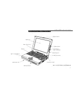
Page 16: ... i t s u 5 Figure 1 6 LifeBook 700 Series with Display Open Display Panel Status Indicator Panel Keyboard ErgoTrac Pointing Device Multi function Bay 1 Multi function Bay 2 Closed Cover Switch Suspend Resume button Built in Microphone Contrast Control Model 735Dx Only Brightness Control Display Panel Latch ...

Page 17: ...ty CapsLock NumLk and Scr Lk Figure 1 6 Suspend Resume Button The Suspend Resume button allows you to sus pend notebook activity without turning off the notebook power and to return it to an active state This feature saves power and is particu larly useful when the notebook is running only on battery power See pages 38 46 and 81 87 for more information on power management Figure 1 6 Closed Cover S...

Page 18: ...ker The built in dual speakers output stereo sound from the notebook Figure 1 7 and Figure 1 8 RIGHT SIDE PANEL COMPONENTS Theft Prevention Lock Slot This is a slot that allows you to attach a physical lock down device Figure 1 8 USB Port This port allows you to connect Universal Serial Bus devices such as external game pads point ing devices keyboards and speakers Figure 1 8 DC Power Jack The DC ...

Page 19: ...will not support an external microphone Figure 1 8 Headphone Jack You can connect headphones or powered external speakers to the headphone jack Figure 1 8 Volume Control The volume control is a knob which provides manual control of the sound level of all audio output from your notebook Figure 1 8 REAR PANEL COMPONENTS RJ 11 Jack This is the jack for attaching a telephone line to the internal modem...

Page 20: ...or SVGA CRT monitor Figure 1 9 Infrared Port The fast IrDA 4Mbps compatible port allows you to communicate with another IrDA compatible infrared device without a cable See pages 46 47 for more information Figure 1 9 C A U T I O N The internal modem is not intended for use with Digital PBX systems Do not connect the internal modem to a digital PBX as it may cause serious damage to the internal mode...

Page 21: ...ity Figure 1 10 Multi function Bay 1 Release Button This is the release to allow removal and instal lation of devices in the Multi function Bay 1 Figure 1 10 Multi function Bay 1 This compartment is accessed from the front of your notebook See Figure 1 6 on page 5 Multi function Bay 2 Release Button This is the release to allow removal and instal lation of devices in the Multi function Bay 2 Figur...

Page 22: ...ecurity Features When you are using your notebook built in hardware control password to gain access to the notebook the actual password will not appear on the screen This is a safety precaution The hardware control security parameters are set from the BIOS setup utility See Security Menu on pages 77 80 for more information on setting and clearing passwords and enabling and disabling built in secur...

Page 23: ...to use your notebook If you wish to access the BIOS setup utility before you go through the condition of use process you must press the F2 key while the Fujitsu logo is still visible If you press the Esc key while the Fujitsu logo is still present you will get a dialog box which will allow you to select which drive is to be used for finding the operating system If you turn off the power without us...

Page 24: ...tered a valid product code When you click on the Finish button the display will flash vari ous screens as the system identifies what hard ware is installed and runs a virus check Time Zone When your notebook has completely identified all of the installed hardware it will display a dialog box for entering which time zone you wish to set the clock to Windows Messaging Once you have selected a time z...

Page 25: ...luding printing and mailing faxing or e mailing 3 Telephone registration by calling the Fujitsu PC service and support line at 1 800 8FUJITSU 1 800 838 5487 P O I N T You will find a Recovery CD ROM packet in your accessories box Please store the packet in a safe place in case there is a loss of data and it becomes necessary to re install your operating system and and or application programs See R...

Page 26: ...e application on a differ ent machine an earlier version of the applica tion or a similar product Manuals In the accessories box you will find manuals for Windows 95 and other pre installed software Software manuals of pre installed software that are not in the accessories box are available online See the help screens of your pre installed software We recommend that you review these manuals for ge...

Page 27: ... Keyboard Angle 19 Status Indicator Panel 19 Power On 23 Power Off 24 Restarting the System 25 Fujitsu Welcome Center 26 Batteries 26 Integrated ErgoTrac Pointing Device 30 Using the Keyboard 32 Volume Control 34 Floppy Disk Drive 34 CD ROM Drive 36 Hard Drive 38 Power Managment 38 Internal Modem 46 Infrared Port 46 Pre installed Software 47 ...

Page 28: ...ou may want to adjust the brightness level of the screen for best visibility To do this adjust the bright ness control slider on the right side of the dis play panel Figure 2 2 You may need to adjust the brightness periodically for different operating environments For model 735Dx only you may also adjust contrast with a contrast control slider that is just below the brightness control Figure 2 1 O...

Page 29: ... 3 The appropriate indicators become visible as you use your notebook Power Indicator The Power indicator tells you when the system is operational It is on steady when there is power to your notebook and blinks when the system is in Suspend mode It goes off when the system has entered Save to Disk mode has entered the Windows 95 pseudo off state or the power is turned off from the power switch C A...

Page 30: ...then the AC Adapter indicator and the Battery indicators will all be Off Battery Indicators The two sets of battery indicators show whether or not the primary Lithium ion battery and or the optional second Lithium ion battery are installed and indicate the condition of each Figure 2 3 Battery 1 is the Lithium ion bat tery which is installed in Multi function Bay 1 and Battery 2 is the Lithium ion ...

Page 31: ...arging and the power switch is Off then the AC Adapter indicator and the Battery indicators will all be off C A U T I O N Turning off the power with the power switch or using the Suspend Resume button when any of the Access indicators are On may cause loss of data and or system errors C A U T I O N A shorted battery is damaged and must be replaced See Figure 2 4 C A U T I O N Batteries subjected t...

Page 32: ...e System icon The system properties dialogue box will be displayed 6 Click on the Device Manager tab The device list will be displayed 7 Click on the to the left of the CD ROM icon The CD ROM drive manufacturer s name and model will be displayed 8 Click on the CD ROM drive manufacturer s name and model 9 Click on Properties The CD ROM drive manufacturer s name and model properties dialogue box wil...

Page 33: ...ou activated it This indicator is inactive if you are using an external keyboard CapsLock Indicator The CapsLock indicator tells you when the key board is set for all capital letters Activate the all capital letters setting by pressing the CapsLock key on the keyboard Deactivate the setting the same way that you activated it This indicator is inactive if you are using an external keyboard Scr Lk I...

Page 34: ...or subject it to shocks or vibration as you risk damaging your notebook When the power switch is turned on your notebook carries out a Power On Self Test POST to check the internal parts and config uration If a fault is found a beep will sound and or an error message will be displayed See Troubleshooting on pages 138 140 Depend ing on the nature of the problem you may be able to continue by starti...

Page 35: ...me button You may also select Shut down the computer and once the power is off turn the power switch to Off for 10 seconds or more and then turn the power switch to On These alternative methods are not recommended C A U T I O N Never turn your notebook off while an application is running Be sure to close all files exit all applications and shut down your operating system prior to turning off the p...

Page 36: ...sed at temperatures that exceed a low of 5 C or a high of 35 C High temperatures not only reduce charging efficiency but can also cause battery deterioration The Charging icon on the Status Indicator panel will flash when you try to charge a battery that is outside its operating temperature range The battery charging capacity is reduced as the battery ages If your battery is running low quickly yo...

Page 37: ...inutes and can vary with the condi tion of your notebook C A U T I O N Do not leave a faulty battery in your notebook It might damage your AC adapter optional auto airline adapter another battery or your notebook itself It may also prevent operation of your notebook by draining all available current into the bad battery C A U T I O N Under federal state or local law it may be illegal to dispose of...

Page 38: ...ct on the Lithium ion batteries which means that you do not need to discharge them completely before recharging A single fully discharged Lithium ion battery will charge in approximately three 3 hours when your notebook is Off or in Suspend mode The charging time from fully discharged for two Lithium ion batteries together is approximately 5 hours when your notebook is Off or in Suspend mode Of co...

Page 39: ...ur data can be maintained for sometime If a power source is not provided promptly the Power indicator will stop flashing and go out and you will have lost the data that was not stored Once you provide power you can continue to use your notebook while an adapter is charging the battery but the battery trickle charges under these conditions If you want to charge the battery more quickly put your not...

Page 40: ... all that is required to operate the ErgoTrac The more pressure you use the faster the cursor will move The second part of the ErgoTrac pointing device the buttons function as mouse but tons and the functions they perform depend on the application you are running Figure 2 6 shows the position of the ErgoTrac pointer and buttons Figure 2 6 ErgoTrac Pointing Device Right Button Left Button Cursor Co...

Page 41: ...n item with the pointing cursor and while keeping the left pointing device button depressed moving the cursor to the desired new location then releas ing the button Figure 2 8 Figure 2 7 Clicking Left Click Left Double Click C A U T I O N If the interval between clicks is too long double clicking will not be executed P O I N T The interval between presses for double clicking and other parameters o...

Page 42: ...nal mouse You may want to try practicing with different adjustments until you find a combination that is comfortable for you USING THE KEYBOARD Your notebook has an integral 86 key keyboard Figure 2 9 The keys perform all the standard functions of a 101 key keyboard and also include Windows 95 keys and other special function keys This section describes only those items specific to your notebook Th...

Page 43: ...e holding down the Fn key allows you to change your selection of where to send your display video Each time you press the combination of keys you will step to the next choice The choices in order are built in dis play panel only external monitor only or both built in display panel and external monitor Windows 95 Keys Your notebook has three Windows 95 keys two Start keys and an Application key The...

Page 44: ...er application software C A U T I O N The ESS AudioRack volume setting sets the maximum volume level of the hard ware volume control knob for Multi function Bay 2 or you can use the optional external floppy disk drive The system will treat any floppy disk drive in exactly the same way regardless of where it is installed For floppy disk drive installation and removal instructions see Multi function...

Page 45: ... Disk P O I N T When there is no floppy disk in the drive the Eject button is flush with the front of your notebook C A U T I O N If you eject the disk while the Floppy Disk Drive Access indicator is On there is a risk of damaging the data on the disk or the disk drive Figure 2 11 Floppy Disk Write Protect Preparing a Floppy Disk for Use Before you can use a new floppy disk you need to prepare it ...

Page 46: ... operate your CD ROM drive unless your notebook is sitting on a flat surface and the adjustment feet are folded against the bottom of the note book Using a CD when the drive is not level may damage the drive or prevent proper operation Care of Floppy Disk Drives and Disks Avoid storing the floppy disk drive and disks in extremely hot and cold locations or in locations subject to severe temperature...

Page 47: ...rtion function you will have to start the CD from your desktop as your note book will not automatically recognize that the CD has been loaded When removing the CD ROM from its case press down on the holder s center while lift ing out the CD ROM by its edges Always handle a CD ROM by the edges and avoid touching the surface Avoid storing any CD ROM in extreme temperatures Do not bend CD ROMs or set...

Page 48: ...em manual for more information on backing up your data files The factory installed software including the operating system can be restored from the Recovery CD ROM which came in the accessories box when you purchased your notebook See Restoring Your Pre installed Software from CD ROM on page 141 for more information Any application software which you have purchased and installed will have to be re...

Page 49: ...dged by activation of the selected mode Which mode is activated is determined by the settings of the BIOS setup utility Power Savings menu The default is Suspend mode See page 84 for how to select Save to Disk mode If your notebook is suspended pushing the Suspend Resume button will return your note book to active operation at the point where it went into suspension The Suspend Resume button is lo...

Page 50: ... menu You can view the menu in icon format along the edge of your desktop by moving the cursor against the edge where you have chosen to keep your PowerPanel toolbar and letting it sit there until the toolbar appears The default position for the toolbar is the left side of the screen but you can move it to whichever edge you like by dragging The power management toolbar has ten power profile choic...

Page 51: ...t appears select PowerPanel Help Topics PowerPanel Customizing To modify your PowerPanel toolbar or create a custom toolbar move your cursor to the PowerPanel toolbar and right click From the menu that appears select Customize Within the Customize dialog box you can choose to have the toolbar display at all times or to use your custom toolbar You can also select from the same menu to Hide the tool...

Page 52: ...Run from the menu which appears You will then get a dialog box for setting the parameters Power Management Off Turns off power management control from Windows 95 and PowerPanel They are turned on from the Start menu Control panel for the Windows 95 management and the Program folder for the PowerPanel management Word Processing Profile The Word Processing profile is a factory installed combination ...

Page 53: ...PowerPanel menu will turn the power to your modem on or off To turn it back on or off select Modem Power Toggle again Video Standby Activation Clicking on the Video Standby button or select ing Video Standby on the PowerPanel menu turns off the power to the display You can return your notebook to normal operation by performing any activity such as pressing a key or touching the ErgoTrac Suspend Mo...

Page 54: ... PC Cards or external devices are in use Save to Disk mode cannot return to the exact state prior to suspension because all of the peripheral devices will be re initialized when the system restarts Save to Disk Mode The Save to Disk function saves the contents of your notebook s system memory to the hard drive whenever you Press the Suspend Resume button until acknowledged with Save to Disk mode e...

Page 55: ...enabled and disabled in the BIOS setup utility See page 83 Standby Mode Standby mode is one of the power management parameters When Standby mode is activated your notebook puts the CPU in low speed operation shuts off the display and turns off the hard drive when there is no activity key stroke pointer action sound generation video display change modem transmission or recep tion etc on your notebo...

Page 56: ... to 36 between the device ports is ideal Dirt or scratches on the lens of your notebook or the other device will degrade performance This is especially true for Fast IrDA applications such as a trans fer to an Ethernet Before you can use the Infrared Port you must set it up in the Advanced Menu Integrated Peripherals submenu in the BIOS setup utility page 68 Since your notebook supports both IrDA ...

Page 57: ... application use their online help SoftPEG MPEG File Player The MPEG file player displays a screen to find the file which you wish to play You can have the list select from limited to particular types of files or display all files Opening the desired file will play it Online help screens are available for more information SoftPEG CD Player This control resembles a CD player front panel and is oper...

Page 58: ...the same way There is also AudioRack recorder software AudioRecorder Online help screens are accessible from the AudioDrive panel of AudioRack32 click on the Help button for more information In the AudioRecorder dialog box click on Help in the top taskbar In AudioRack32 the AudioDrive panel lets you turn on and off the available functions When you left click on a button it will activate When a fun...

Page 59: ...ak facing the keyboard from about one 1 foot away McAfee VirusScan Running your McAfee VirusScan program after loading data or programs from a floppy disk CD ROM modem data transfer or infrared data transfer is a precaution that will protect the data on your hard drive from contamina tion or destruction See your VirusScan online help screens for information on how and when to run this program ...

Page 60: ...Utility 55 Main Menu Setting Standard System Parameters 56 Advanced Menu Setting Device Feature Controls 65 Security Menu Setting the Security Features 77 Power Savings Menu Setting Power Management Feature Controls 81 Boot Menu Selecting the Operating System Source 88 Exit Menu Leaving the Setup Utility 90 Setting Up Your Save To Disk File Allocation 93 ...

Page 61: ...nal devices such as hard drives floppy disk drives CD ROM drives and PC Cards The most com monly assigned drive designators are listed below If you add other devices the drive desig nators may be different See your operating sys tem manual for setting drive designations Drive Designators A Floppy disk drive Installable in either of the multi function bays of your notebook or use the external flopp...

Page 62: ...e your operating system manual Change the primary boot device Change the power mangement parameter settings For a more convenient process see the PowerPanel on pages 40 43 Change a port address or other parameter Change an audio parameter setting Change the selection of whether to use the built in display an external monitor or both For a more convenient process see the Fn key on page 33 Change th...

Page 63: ...o enter the setup utility press the F2 key 4 When the setup utility starts with a fault pre sent the system displays the following message Warning Error message Continue 5 Press any key to enter the setup utility The system will then display the Main Menu with current parameters values Entering the Setup Utility After a Configuration Change or System Failure If there has been a change in the syste...

Page 64: ... or to go to the next lower selection 4 To activate a submenu press the Enter key P O I N T Selecting a field causes a help message about that field to be displayed on the right hand side of the screen P O I N T Pressing the Enter key with the highlight on a selection that is not a submenu or auto selection will cause a list of all options for that item to be displayed Pressing the Enter key or Es...

Page 65: ... 55 Table 3 1 shows the names of the menu fields for the Main menu all of the options for each field the default settings and a description of the field s function and any special information needed to help understand the field s use P O I N T System Time and System Date can also be set from your operating system without using the setup utility Use the calendar and time icon on your Control panel ...

Page 66: ...he Tab key and or Shift Tab keys Diskette A 1 44Mb 3 5 Disabled 1 44Mb 3 5 Sets the format for floppy disk drive A if it is installed IDE Adapter 0 Master Selects the IDE Adapter 0 2167 MB Displays the capacity of the internal hard drive which is on this Master submenu interface and when selected opens the submenu which allows you to change the interface specifications to suit your particular hard...

Page 67: ... the Boot Options submenu Options submenu System Memory 640 KB Displays the size of system memory which is detected automatically and cannot be changed by the setup utility Extended Memory 31 MB Displays the size of extended memory which is detected automatically and cannot be changed by the setup utility Menu Field Options Default Description ...

Page 68: ...he capacity displayed at the top of the screen as well as on Main menu Follow the instructions for Navigating Through the Setup Utility to make any changes See page 55 Table 3 2 shows the names of the menu fields for the IDE Adapter submenu all of the options for each field the default settings and a description of the field s function and any special information needed to help understand the fiel...

Page 69: ... 39 Cylinders Available to A number between 0 Sets the number of cylinders for the drive This field can be change only when and 65 535 changed by incrementing pressing the Spacebar or by typing in Type User Displayed the number for Type Auto when a hard drive has been detected and Type any number Table 3 2 Fields Options and Defaults for the IDE Adapter Submenu C A U T I O N Even if the item help ...

Page 70: ... any number Sectors Track Available to A number between 0 and 63 Sets the number of cylinders for the drive This field can be change only when Type changed by incrementing pressing the Spacebar or by typing in User Displayed for Type the number Auto when a hard drive has been detected and Type any number Write Precomp None A number between Sets the amount of data compression the interface will use...

Page 71: ...nabled Disabled Enables or disables logical Block Addressing in place of Cylinder Available to change only Head Sector addressing when Type User None Rsvr or a number Displayed for Type CD or Auto with a hard drive detected Transfer Mode Standard Fast PIO 1 Selects the data movement method for the drive Available to change Fast PIO 4 only when Type User None Rsvr or a number Displayed for Type CD ...

Page 72: ...nternal hard drive becomes Drive D and the CD ROM becomes Drive C and all other drive designations shift as necessary The boot sequence ignores the new drive designations however your application software will use the new designations C A U T I O N Be careful of the operating environment when booting from a CD ROM or you may overwrite files by mistake Boot Options Submenu The Boot Options submenu ...

Page 73: ...e operating system is loaded Boot time Enabled Disabled Disabled Enables and disables the display of a screen containing diagnostic Diagnostic Screen information as it is detected by the Power On Self Test POST Menu Field Options Default Description Table 3 3 Fields Options and Defaults for the Boot Options Submenu Exiting from the Main Menu When you have finished setting the parameters on this me...

Page 74: ...ld s use ADVANCED MENU SETTING DEVICE FEATURE CONTROLS The Advanced Menu allows you to Set the I O addresses for the serial and parallel ports Set the communication mode for the parallel port Set an audio function I O address interrupt level and DMA channel Select between the display panel and an external CRT display Enable or disable compensation for your display Set the I O address for PCIC Set ...

Page 75: ...llows setting external and internal keyboard and mouse parameters Audio Features When selected opens the Audio Features submenu which allows setting the hardware address and interrupt levels of audio functions and enabling or disabling the MIDI joystick port Video Features When selected opens the Video Features submenu which allow setting of the display parameters including routing of video signal...

Page 76: ... before making any changes in the event that a restoration is required See your hardware and software documentation as well as the setup utility to determine settings limitations etc Integrated Peripherals Submenu of the Advanced Menu The Integrated Peripherals submenu provides the ability to set the I O addresses and interrupt levels for ports of your notebook Follow the instructions for Navigati...

Page 77: ... level 3E8 IRQ 4 2E8 IRQ 3 3F8 IRQ 11 2F8 IRQ 10 3E8 IRQ 11 2E8 IRQ 10 Disabled IR Port 3F8 IRQ 4 2F8 IRQ 3 3E8 Disabled Sets the infrared port address and interrupt level IRQ 4 2E8 IRQ 3 3F8 IRQ 11 2F8 IRQ 10 3E8 IRQ 11 2E8 IRQ 10 Disabled IR Mode Standard Fast DMA Standard Sets the infrared port mode CHANNEL 1 Fast DMA CHANNEL 3 Table 3 5 Fields Options and Defaults for the Integrated Peripheral...

Page 78: ... notebook is connected to a parallel printer it can transfer data and control information to the printer and the printer can transfer back status and error information to your notebook Output Only Half Duplex information transferred in only one direction from your notebook to the printer or similar device ECP Mode allows communication with the ECP class of parallel I O devices Diskette Controller ...

Page 79: ...Routing Disabled Auto select Auto select Sets how the PCI interrupt will be routed IRQ3 IRQ4 IRQ5 IRQ7 IRQ9 IRQ10 IRQ11 Internal Modem Enabled Disabled Enabled Enables and disables the internal modem Table 3 5 Fields Options and Defaults for the Integrated Peripherals Submenu ...

Page 80: ...ntegrated and external mouse and keyboard Follow the instructions for Navigating Through the Setup Utility to make any changes See page 55 Table 3 6 shows the names of the menu fields for the Keyboard Mouse submenu all of the options for each field the default settings and a description of the field s function and any special information needed to help understand the field s use Figure 3 6 Keyboar...

Page 81: ...and have it immediately recognized and active Internal Pointing Device Auto Disabled Auto Disabled Sets the device controlling the mouse cursor on the screen Always Always Enabled Enabled makes the ErgoTrac pointing device always enabled whether there is an external mouse or not Auto Disabled makes the ErgoTrac pointing device turn off when an external pointing device is connected to the PS 2 port...

Page 82: ...llow the instructions for Navigating Through the Setup Utility to make any changes See page 55 Table 3 7 shows the names of the menu fields for the Audio Features submenu all of the options for each field the default settings and a description of the field s function and any special information needed to help understand the field s use Figure 3 7 Audio Features Submenu P O I N T All I O addresses ...

Page 83: ...rational or accessible Audio FM Base Address 388 38C 390 394 388 Sets the base address for FM synthesizer functions Audio IRQ Number 5 7 9 10 11 5 Sets the interrupt level for audio functions Audio DMA0 Channel 0 1 3 5 1 Sets the DMA0 audio channel Audio DMA1 Channel None 0 1 3 5 5 Sets or disables the DMA1 audio channel Table 3 7 Fields Options and Defaults of the Audio Features Submenu of the Ad...

Page 84: ...splay parameters Follow the instructions for Navigating Through the Setup Utility to make any changes See page 55 Table 3 8 shows the names of the menu fields for the Video Features submenu all of the options for each field the default settings and a description of the field s function and any special information needed to help understand the field s use Figure 3 8 Video Features Submenu ...

Page 85: ... enabled displays with less than 800 x 600 pixel resolution will still cover the entire screen Table 3 8 Fields Options and Defaults for the Video Features Submenu of the Advanced Menu Exiting from the Advanced Menu When you have finished setting the parameters on the Advanced Menu you can either exit from setup utility or move to another menu If you wish to exit from setup utility press the Esc k...

Page 86: ... to view the current data security configuration Follow the instructions for Navigating Through the Setup Utility to make any changes See page 55 Table 3 9 shows the names of the menu fields for the Security menu all of the options for each field the default settings and a description of the field s function and any special informa tion needed to help understand the field s use The default conditi...

Page 87: ...ing System Disabled to be displayed If this happens restart the computer by turning off and on the power with the power switch and use the correct password on reboot P O I N T If you make an error when reentering the password a Warning will be displayed on the screen To try again press the Enter key and then retype the password Press the Esc key to abort the password setting process C A U T I O N ...

Page 88: ...ntering characters in the Enter New Password field and in the Re enter New Password field When a Supervisor Password is set it must be used to access the BIOS setup utility Diskette access All Supervisor Only All Sets the floppy disk access to be secured for access only with Supervisor s password or by all users with a password The default is Supervisor Only but if no Supervisor password is set it...

Page 89: ... function Fixed Disk Boot Sector Normal Write Protect Normal Sets write protection for the sector of the boot disk which contains the operating system When set to Write Protect the BIOS will prevent any application from writing into the sector of the internal hard drive containing the operating system When set to Normal there is no BIOS protection of the operating system Table 3 9 Fields Options a...

Page 90: ...NU SETTING POWER MANAGEMENT FEATURE CONTROLS The Power Savings menu allows you to set and change the power management parameters Follow the instructions for Navigating Through the Setup Utility to make any changes See page 55 Table 3 10 shows the names of the menu fields for the Power Savings menu all of the options for each field the default settings and a descrip tion of the field s function and...

Page 91: ...oller and drive motor If you choose a factory installed combination of parameters this field will display the setting If you choose to customize the parameters you will be able to set this yourself The options available vary from Off which has no inactivity shutoff to 20 minutes Video Timeout 30 seconds to 20 minutes Off Off Sets the length of time without any user input device activity before the...

Page 92: ...ngth of time without any user input device activity before the CPU is set to half speed and the display and the hard drive are turned off If you choose a factory combination of parameters this field will display the setting If you choose to customize the parameters you will be able to set this yourself Auto Suspend Timeout 5 to 60 minutes Off 15 Minutes Sets the length of time without any I O acti...

Page 93: ...memory and operating parameters are loaded from the hard drive C A U T I O N In Save to Disk mode there is no indication on the Status Indicator to let you know you are suspended rather than shut off from the power switch You may want to make a habit of always trying the Suspend Resume button before using the power switch Auto Save to Disk Off After 1 Hour Off When set to After 1 Hour your noteboo...

Page 94: ...seconds Each segment of the time is set separately either by incrementing or by typing in the numbers You move between the segments with the Tab key or the Shift Tab keys This only applies when Resume on Time is set to On Advanced Features When selected opens the Advanced Features submenu which allows setting additional power saving parameters Factory Installed Values for Power Saving Profiles Tab...

Page 95: ...uctions for Navigating Through the Setup Utility to make any changes See page 55 Table 3 11 shows the names of the menu fields for the Video Features submenu all of the options for each field the default settings and a description of the field s function and any special information needed to help understand the field s use Figure 3 11 Advanced Features Submenu ...

Page 96: ...ing Idle mode LCD Backlight Mode Low Power Standard Low Power Sets the CPU speed during Video timeout and Lid Closure Suspend activation Serial Mouse Activity Enabled Disabled Disabled Enables and disables having activity on the serial port cause the system to reactivate from inactivity timeouts Table 3 11 Fields Options and Defaults for the Advanced Features Submenu of the Power Savings Menu Exit...

Page 97: ...er in which the BIOS searches sources for the operating system Table 3 12 shows the names of the menu fields for the Boot menu all of the options for each field the default settings and a description of the field s function and any special information needed to help understand the field s use Figure 3 12 Boot Menu ...

Page 98: ...n Ôcursor keys and then press the or key to change the order number for that source Be sure to save your changed order when you exit the BIOS setup utility 2 Diskette Drive 3 CD ROM Drive Table 3 12 Fields Options and Defaults for the Boot Menu Exiting from Boot Menu When you have finished setting the search sequence order with the Boot menu you can either exit from the setup utility or move to an...

Page 99: ...tions for Navigating Through the Setup Utility to make any changes See page 55 Table 3 13 shows the names of the menu fields for the Exit menu all of the options for each field the default settings and a description of the field s function and any special information needed to help understand the field s use Figure 3 13 Exit Menu ...

Page 100: ...it the setup utility with out writing to the BIOS memory When the BIOS recognizes this selection it will load the operating system and begin operation A message Setup Warning Configuration Changes have not been saved Save before exiting Yes No will be displayed Get Default Values Selecting Get Default Values will load the factory preset default values for all menu fields then display the message S...

Page 101: ...return to another menu follow the directions in the Navigating Through the Setup Utility Section See page 55 Save Changes Selecting Save Changes will cause the new settings in all menus to be written to the BIOS memory Setup Confirmation Save Changes now Yes No When confirmed the setup utility will return to the Exit menu To return to another menu follow the directions in the Navigating Through th...

Page 102: ...uch space is needed to per form the Save to Disk function with the current memory configuration and how much unused space is available on the internal hard drive To find out how much space is needed to perform the Save to Disk function with the current memory configuration and how much unused space is available on the internal hard drive do the following 1 Restart your notebook in MS DOS mode 2 At...

Page 103: ...e needed to support the Save to Disk function with the current memory configuration If you have had a read or write error when you tried to perform a Save to Disk operation you can re allocate space to compensate for bad blocks on your drive To do this 1 Go to the MS DOS prompt 2 Type PHDISK REFORMAT FILE 3 Press the Enter key 4 The utility will re create the Save to Disk file called SAVE2DSK BIN ...

Page 104: ...allel Port Devices 105 Serial Port Devices 105 USB Devices 105 Microphone 105 Stereo Line In Devices 105 Headphones 105 Telephone Lines 106 Mouse or Keyboard 106 External Monitor 106 Theft Prevention Lock 106 External Installation of a Floppy Disk Drive 107 Memory Upgrade Module 108 LANdock 111 Port Replicator 115 ...

Page 105: ...t headphones or powered speakers A PS 2 port on the right side of your note book allows you to connect an external mouse keyboard or numeric keypad An external floppy disk drive port on the right side of your notebook allows you to attach an external floppy disk drive when the Multi function bays are being used for other purposes A USB port in the right side of your note book allows you to connect...

Page 106: ...t unit in Suspend mode See Power Off on pages 24 25 and Bridge Battery on page 27 C A U T I O N Do not use your notebook with either of the Multi function bays empty It may damage your notebook Figure 4 1 Multi function Bay Modules Floppy Disk Drive Lithium ion Battery Second Hard Drive CD ROM Drive Floppy Disk Drive Device Adapter for Bay 2 Lithiun ion Battery Device Adapter for Bay 2 Bay 1 Modul...

Page 107: ...notebook from either bay Your notebook also supports a dual battery configuration with a Lithium ion battery in both bays at the same time The optional sec ond battery must be purchased separately It does not support multiple floppy disk drives but has three different places to install one To Install or Remove a Device in Multi function Bay 1 1 Close all files and exit all applications 2 Turn off ...

Page 108: ...the module connector toward the back of your notebook align the grooves on the side of the device with the tracks in the side of the bay Figure 4 3 6 Slide the module toward the back of your notebook until it clicks into place To Install or Remove a Device in Multi function Bay 2 1 Close all files and exit all applications 2 Turn off power to your notebook close the display and remove the AC adapt...

Page 109: ... loading a CD in your CD ROM drive and caring for CD ROMs see Section Two pages 36 37 3 Set the device adapter for Multi function Bay 2 on top of the Multi function Bay 1 device and adjust until the finger ridge shows through the hole in the device adapter for Multi function Bay 2 and the alignment pins on the Multi function Bay 1 device fit in the small round holes of the device adapter for Multi...

Page 110: ...must be installed or removed with the power off Lithium ion Battery Your Lithium ion battery is durable and long lasting but should not be exposed to extreme temperatures high voltages chemicals or other hazards Optional Second Hard Drive The optional second hard drive is durable but you must treat it with care Please pay attention to the following points The drive rotates the disk at very high sp...

Page 111: ...gal to dispose of batteries by putting them in the trash Please take care of our environment and dispose of batteries properly Check with your local government authority for details regarding recycling or disposing of your old battery or contact your support representative at 1 800 8FUJITSU 1 800 838 5487 C A U T I O N Data may be lost and or system errors introduced if the warm swap is not perfor...

Page 112: ...onged exposure to direct sunlight or excessive heat Keep the cards dry Do not flex or bend the cards and do not place heavy objects on top of them Do not force cards into the slot Avoid dropping cards or subjecting them to excessive vibration Figure 4 9 Installing and Removing a PC Card Eject Button Slot 0 Eject Button Slot 1 PC Card Lock PC CARDS PC Cards perform a wide variety of functions and a...

Page 113: ...PC Cards will not work when all possible devices are enabled If a PC Card is not recognized you will need to open the Control panel the System fold er and then the Device Manager and choose a device to disable so that the resources can be used by the PC Card C A U T I O N Some PC Cards can only be installed or removed with the power in Suspend mode some only with power Off Please check the card do...

Page 114: ... that the connector is the right size and aligned then push in until it is fully seated When it is seated tighten the hold down screws one on each end of the connector See Figure 1 9 on page 8 SERIAL PORT DEVICES To connect an RS 232C device to the serial port be sure that the connector is the right size and aligned then push in until it is fully seated When it is seated tighten the hold down scre...

Page 115: ...ttom of your note book and push it in until the connector seats A mouse keyboard or keypad may be installed and automatically recognized by your notebook without restarting or changing setups See Figure 1 8 on page 7 EXTERNAL MONITOR You may install an external monitor on the external monitor port on the rear panel of your notebook Make sure that the wide side of the connector is up and attach it ...

Page 116: ...ches Figure 4 10 External Installation of a Floppy Disk Drive External Floppy Disk Drive Port External Floppy Disk Drive Connector Cover Connector Release Button Connector Release Button External Floppy Disk Drive EXTERNAL INSTALLATION OF A FLOPPY DISK DRIVE To install a floppy disk drive externally you must purchase an optional external floppy disk drive To connect a floppy disk drive externally ...

Page 117: ... toward you 4 Remove the screws at the front of the memory upgrade module compartment See Figure 4 11 5 Remove the cover by tilting the front edge up and then pulling forward until the tabs on the cover are free See Figure 4 11 6 Remove the memory upgrade module from the static guarded sleeve MEMORY UPGRADE MODULE Your notebook has 16MB or 32MB of installed SDRAM To increase your memory capacity y...

Page 118: ... the compartment The notch on the module should be on the right with the part side up and the connector pointing toward the front of the notebook and aligned with the notch in the connector inside the compartment Figure 4 12 8 Insert the memory upgrade module at a 45 angle Figure 4 12 Press the connector edge of the module firmly down and into the con nector 9 Press the memory upgrade module down ...

Page 119: ...y Memory 16MB 640 K 15M 24MB 640K 23 5M 32MB 640 K 31 7M 48 MB 640 K 48 5M 64 MB 640 K 64M 96 MB 640 K 97M Figure 4 13 LANdock Front View LANdock unit Leveling Alignment Foot Alignment Notches Docking Connector Telephone Connector Undock Request Button Docked LED Ready to Undock LED Docking Release Lever Docking Alignment Pins Checking the Computer Recognition of New Memory Capacity When you have ...

Page 120: ...rear panel of your notebook See Figure 1 9 on page 8 4 Make sure that the adjustment feet are flat against the bottom of the notebook and the covers of the connectors both rear panel and right side panel are closed 5 Make sure that the slide cover in the rear panel is completely open If the total memory displayed is not what you believe it should be check that your memory upgrade module is properl...

Page 121: ...h as appropriate When setting up for the first time you must use the power switch Connecting Devices to the LANdock or Port Replicator Connect devices to your LANdock or Port Replicator in exactly the same way you would your notebook Figure 4 14 shows the location of LANdock ports and jacks Figure 4 17 shows the location of the Port Replicator ports and jacks Remember that on the LANdock and the P...

Page 122: ...e docking device with the operating system active You may cause a loss of data and a system error when you restart your notebook Creating the Windows 95 Docked Configuration This is only necessary when you change note book configuration and dock your notebook for the first time 1 Install your notebook in the LANdock or Port Replicator 2 Turn on the power The operating system will automatically beg...

Page 123: ...e entire screen Future docking with Windows 95 can be done in Suspend mode Save to Disk mode or with the power off and the system will automatically detect whether you are docked or not when you resume operation Undocking should only be done with power off or in PC Eject mode Figure 4 16 Port Replicator Front View Port Replicator Leveling Alignment Foot Alignment Notches Docking Connector Telephon...

Page 124: ...ndows 95 has the addition to the Start Menu of a PC Eject choice between the Suspend mode and Shutdown selections Use the PC Eject choice to enable the undocking of your LifeBook Both an external mouse and an external key board can be connected at the same time Be sure to plug them into the correct PS 2 ports Using Your Notebook While It Is Installed In the Port Replicator There are a few differen...

Page 125: ... n g S e c t i o n F i v e Identifying the Problem 118 Specific Problems 119 Power On Self Test Messages 138 Emergency CD ROM Tray Release 141 Modem Setup and Commands 141 Restoring Your Pre installed Software from CD ROM 141 ...

Page 126: ...plugged in properly You can also disconnect such devices thus eliminating them as possible causes of failure 5 Turn on your notebook using the power switch Make sure it has been off at least 10 seconds before you turn it on 6 Go through the boot sequence 7 If the problem has not been resolved refer to the problem guide table which follows for more detailed troubleshooting information Page 119 has ...

Page 127: ...ebook Your support representative will then use the service computer to call your notebook and perform diagnostic tests to find the nature of your problem Messages will be displayed on the screen explaining what is being done and giving any instructions that you need User Problem Guides When you have problems with your notebook try to find the symptoms under the Problem column of the table for the...

Page 128: ...OS setup utility Audio Features submenu of the Advanced menu to the default values See pages 73 74 5 Software driver is not configured correctly 5 Refer to your application and operating system documentation for help CD ROM Drive Problems Notebook fails to recognize CD ROM 1 Shipping card is still in the CD ROM drive tray 1 Remove shipping card and replace CD in tray 2 CD ROM is installed with lab...

Page 129: ...on pages 63 64 7 Windows CD auto insertion function 7 Start the CD from the desktop or is disabled application software or re enable the WindowsCD auto insertion function See CD ROM Access Indicator on pages 21 22 for more nformation The CD ROM Access indicator on the Status 1 The Windows CD auto insertion function 1 This is normal Indicator panel blinks at regular intervals when is active and is ...

Page 130: ...k is not loaded correctly 2 Eject floppy disk check orientation and re insert See Floppy Disk Drive on pages 34 35 3 BIOS setup utility has Diskette 3 Revise the setup utility Main menu settings Controller Disabled See Main Menu on pages 56 57 4 The floppy disk drive may not be 4 Remove and re install your floppy disk drive properly installed See Multi function Bays on pages 97 100 or External Ins...

Page 131: ...application when a bootable CD ROM was is in use by the operating system When the used to start the notebook operating system is booted from a CD ROM drive designations are automatically adjusted See IDE Adapter Submenu on pages 59 62 3 Security is set so operating system can not 3 Verify your password and security settings be started without a password See Security menu on pages 77 80 Keyboard or...

Page 132: ...nto the PS 2 Keyboard port Figure 4 14 on page 111 and Figure 4 17 on page 115 You have connected an external keyboard or a 1 Your operating system software is not setup 1 Check your device and operating system mouse and it seems to be locking up the system with the correct software driver for that device documentation and activate the proper driver 2 Your system has crashed 2 Restart your system ...

Page 133: ...ion tion for additional information is in use Parallel Serial and USB Device Problems You have installed a parallel port device 1 The device is not properly installed 1 Remove and re install the device a serial port device or a USB device See Parallel Port Devices on page 105 Your notebook does not recognize the device Serial Port on Devices on page 105 or USB or the device does not seem to work p...

Page 134: ...d in the PC Card slot 1 The card is not properly installed 1 Remove and re install the card does not work or is locking up the system See PC Cards on pages 103 105 2 The card may have been installed with an 2 Close your application and application running and your notebook restart your notebook doesn t know it s there 3 Your software may not have the correct 3 See your software documentation softw...

Page 135: ...l to determine the presence and condition of the batteries See pages 20 21 Install the primary battery if it is not installed or a Power adapter if all batteries are dead or unavailable See pages 97 100 and 10 11 2 The primary battery is installed but is 2 When the batteries are dead there will be a completely discharged there is no optional beep when the power switch is turned on second battery i...

Page 136: ...pages 20 21 Move the AC cord to a dif ferent outlet check for a line switch or tripped circuit breaker for the AC outlet if you are using an auto airline adapter in a car make sure the ignition switch is in the On or Accessories position 4 The primary battery is installed but is 4 When the battery is dead there will be completely discharged there is no optional a beep when the power switch is turn...

Page 137: ...Use the Status Indicator panel to verify the Power adapter AC or auto airline installed presence and condition of the batteries See Figure 2 3 on page 20 Install a Power adapter or install a battery in one of the Multi function bays in the front of your notebook See Multi function Bay Devices on pages 97 100 If the battery is not charged use a Power adapter until it is charged 7 The primary batter...

Page 138: ...r management parameters are set 1 Use the keyboard or pointer and if that does for auto timeouts which are too short for not restore operation push the Suspend your operating needs Resume button Check the PowerPanel set tings or close your applications and go to the setup utility Power Savings menu and adjust the timeout values to better suit your operation needs See the PowerPanel on pages 40 43 ...

Page 139: ...es are dead 1 When the batteries are dead there will be a beep when the power switch is turned on and the notebook will immediately go into Dead Battery Suspend mode See page 29 Replace the battery with a charged one or install a Power adapter 2 No batteries are installed 2 Install a charged battery See Multi function Bay Devices on pages 97 100 3 The batteries are improperly installed 3 Verify th...

Page 140: ...according to your operating needs 3 The brightness is turned all the way up 3 Turn down the brightness adjustment The higher the brightness the more power your display uses 4 The batteries are very old 4 Replace the batteries 5 The batteries have been exposed to 5 Replace the batteries high temperatures 6 The batteries are too hot or too cold 6 Restore the notebook to normal operating See Batterie...

Page 141: ...p utility 1 Set the operating source by pressing the Esc power on information but fails to load are not compatible with your configuration key while the Fujitsu logo is on screen or use the operating system the F2 key and enter the setup utility and adjust the source settings from the Boot menu on page 89 2 You have a secured system requiring a 2 Make sure you have the right password password to l...

Page 142: ...ting the BIOS setup utility utility returning it to previous settings 2 The BIOS CMOS hold up battery has failed 2 Contact your support representative for repairs This is not a user serviceable part but has a normal life of 3 to 5 years Video Problems The built in display is blank 1 Something is pushing on the Closed 1 Clear the Closed Cover switch when you turn on your notebook Cover switch See F...

Page 143: ...eout 5 The notebook turned on with a series of beeps 5 Power On Self Test POST has detected a failure which does not allow the display to operate Contact your support representative The display goes blank by itself after you 1 The notebook has gone into Video timeout 1 Use the keyboard or pointer and if have been using it Standby mode Suspend mode or Save to Disk that does not restore operation pu...

Page 144: ... tiny and few in number 1 This is normal do nothing this is normal for a large LCD display 2 If the spots are numerous or large enough to 2 Display is faulty contact your interfere with your operation needs support representative The application display uses only a portion 1 You are running an application that does not 1 Display compression gives a clearer but of your screen and is surrounded by a...

Page 145: ... page 106 3 Your operating system software is not setup 3 Check your device and operating system with the correct software driver for that device documentation and activate the proper driver 4 Your external monitor is not compatible 4 See your monitor documentation and the with your notebook External Monitor Support portions of Appendix A on pages 148 157 Miscellaneous Problems An error message is...

Page 146: ...erly If you have an installed memory upgrade module verify that the module is properly installed If it is properly installed you may want to check your Windows Setup to be sure it is not using unavailable memory until you can contact your support representative nnnn Extended RAM Passed Where nnnn is the amount of memory in kilobytes successfully tested Failing Bits nnnn The hex number nnnn is a ma...

Page 147: ... unlikely case that you see this message you may have some display problems You can continue operating but should contact your support representative for more information Keyboard controller error The keyboard con troller test failed You may have to replace your keyboard or keyboard controller but may be able to use an external keyboard until then Contact your support representative Keyboard error...

Page 148: ...etup Utility default values or reconfigure your Setup Utility every time you turn off your notebook This battery has an expected life of 2 to 3 years System BIOS shadowed System BIOS copied to shadow RAM System CMOS checksum bad run SETUP BIOS CMOS RAM has been corrupted or modified incorrectly perhaps by an application program that changes data stored in BIOS memory Run Setup and reconfigure the ...

Page 149: ...isplayed on your screen to keep you informed of the actions of your modem The operating system and application software may suppress display of the result codes Examples of result codes are OK NO CARRIER NO DIALTONE CONNECT 56000 Connection complete at 56 000 bps ERROR FAX RING This means an incoming call BUSY NO ANSWER When using the internal modem with applica tions which are not factory install...

Page 150: ...C a r e a n d M a i n t e n a n c e S e c t i o n S i x Care and Maintenance 144 Caring for Your Notebook 144 Increasing Battery Life 145 Caring for Your Batteries 145 ...

Page 151: ... the notebook and the battery packs CARING FOR YOUR NOTEBOOK The LifeBook 700 Series is a durable but sensitive electronic device Treat it with respect and care Make a habit of transporting it in a suitable carrying case Keep it away from food and beverages If you accidentally spill liquid on your notebook 1 Turn it off 2 Position it so that the liquid can run out 3 Let it dry out for 24 hours or ...

Page 152: ...r maximum battery life 5 Put your notebook in Suspend mode when it is turned on and you are not actually using it 6 Limit your CD ROM access 7 Disable the Windows 95 CD automatic insertion function See page 20 8 Always use fully charged batteries CARING FOR YOUR BATTERIES If your notebook is to be stored for a month or longer turn the machine off and remove all Lithium ion batteries Store your not...

Page 153: ... o s s a r y A p p e n d i c e s Appendix A Specifications 148 Warranty 148 LifeBook 735DX Specifications 148 LifeBook 755TX Specifications 151 LifeBook 765TX Specifications 154 Approvals 157 Popular Accessories 157 Appendix B Glossary 159 ...

Page 154: ...le in a single DIMM dual in line memory mod ule slot in a compartment in the bottom of the notebook SDRAM Modules are recommended but EDO RAM Modules will work Fujitsu product numbers 16MB SDRAM FPCEM05 32MB SDRAM FPCEM06 64MB SDRAM FPCEM07 Installing an EDO RAM Module will cause your entire system to operate at slower EDO timing 8MB EDO RAM FPCEM01A 16MB EDO RAM FPCEM02A 32MB EDO RAM FPCEM03 64MB...

Page 155: ...95 by ESS Technology Inc SoftPEG by CompCore Multimedia Inc Others dependent on options purchased Input Output Connections One Type III two Type I II PC Card slot PCMCIA Standard 2 1 with CardBus sup port Zoomed Video support via Slot 0 One 6 pin mini DIN PS 2 compatible connec tor for external keyboard external mouse or external numeric keypad One 25 pin D SUB two way Centronics type connector fo...

Page 156: ...ok off or in suspend mode in about three 3 hours Standard charge normal use with limited CD and hard drive access in about nine 9 hours C A U T I O N Actual battery life will vary based on screen brightness applications features power management settings battery conditioning and other customer preferences CD ROM or hard drive usage may also have a significant impact on battery life Dual Battery Co...

Page 157: ...chnology L1 and L2 cache PCI bus architec ture and CardBus architecture Memory System Memory 32MB SDRAM L1 Cache Memory 32KB within CPU L2 Cache Memory 256KB Pipeline Burst SRAM Expansion Memory 16MB 32MB and 64MB SDRAM Modules extend system memory up to 96MB installable in a DIMM dual in line memory module slot in a compartment in the bottom of the note book SDRAM Modules are recommended but EDO ...

Page 158: ...er for Bay 2 Fujitsu Model FPCBYA01 Pre Installed Software Microsoft Windows 95 LapLink by Traveling Software MegaPhone by Cypress Research VirusScan by McAfee Associates Audio Rack 32 for Windows 95 by ESS Technology Inc SoftPEG by CompCore Multimedia Inc Others dependent on options purchased Input Output Connections One Type III two Type I II PC Card slot PCM CIA Standard 2 1 with CardBus suppor...

Page 159: ...eyboard Support PS 2 compatible External Numeric Keypad Support PS 2 compatible External Mouse Support PS 2 compatible Power Batteries One modular Lithium ion battery Fujitsu Model FPCBP11 Rechargeable 10 8V 3300 mAh Operating time of up to 3 hours Rapid charge notebook Off or in Suspend mode in about three 3 hours Standard charge normal use with limited CD and hard drive access in about nine 9 ho...

Page 160: ...lectro Static Discharge ESD 9 kV Theft Prevention Lock Lock slot on the right side panel for use with physical restraining security systems The lock ing system by Kensington is recommended LifeBook 765Tx Specifications Microprocessor Intel Pentium P55CSLM 166MHz with MMX technology L1 and L2 cache PCI bus architec ture and CardBus architecture Memory System Memory 32MB SDRAM Optional Auto Airline ...

Page 161: ...mVp p or less minimum impedance 10K Ohms Two built in speakers 28 mm diameter Stereo One built in monaural microphone Communication Internal 56K fax data voice modem 56 Kbps data voice transmission 14 4 Kbps fax trans mission DSVD See page 3 for caution on modem One IrDA compatible infrared port 4 Mbps Video MPEG 1 video data decompression software Zoomed Video support via PC Card Slot 0 Device Ad...

Page 162: ...lution 64K colors 640 x 480 pixel resolution 16M colors Keyboards Built in keyboard with all functions of 101 key PS 2 compatible keyboards Total number of keys 86 Function keys 12 F1 through F12 Feature extension key Fn Windows 95 keys 3 two Start keys and one Application key Key pitch 19 mm Key stroke 3 mm Built in ErgoTrac pointing device with left and right buttons Built in palmrest External K...

Page 163: ...297 mm x 246 mm x 58 mm Approvals Emissions FCC Part 15 FCC Part 68 FTZ Safety UL C UL CSA FCC Certification See statement at the front of this User s Guide DOC Industry Canada Certification See statement at the front of this User s Guide Popular Accessories Other accessories are available contact your authorized Fujitsu reseller Optional second modular Lithium ion battery Fujitsu Model FPCBP11 Op...

Page 164: ...ANdock is powered from a power adapter which is included with the LANdock Fujitsu Model FPCAC06 Port Replicator Fujitsu Model FPCPR07 The Port Replicator provides connections for RS 232C Serial device Parallel device VGA SVGA XGA monitor Mouse PS 2 Keyboard PS 2 Telephone line RJ 11 Two USB devices External floppy disk drive Microphone Stereo Line In The Port Replicator is powered from a power ada...

Page 165: ...tes Boot To start up a computer and load its operating system from disk ROM or other storage media into RAM Bus An electrical circuit which passes data between the CPU and the sub assemblies inside your computer Byte 8 bits of parallel binary information Cache Memory A block of memory built into the micro processor which is much faster to access than your system RAM and used in specially struc tur...

Page 166: ...eprogrammed value to be used if you fail to set your own DIMM Dual in line memory module Disk A spinning platter of magnetic data storage media If the platter is very stiff it is a hard drive if it is highly flexible it is a floppy disk if it is a floppy disk in a hard housing with a shutter it is commonly called a diskette Disk Drive The hardware which spins the disk and has the heads and control...

Page 167: ...a 4 bit binary number 0 9 A B C D E F Example 2F in hexadecimal 00101111 in binary 47 in decimal I O Input Output Data entering and leaving your computer in electronic form I O Port The connector and associated control circuits for data entering and leaving your computer in electronic form IDE Intelligent Drive Electronics A type of control interface for a hard drive which is inside the hard drive...

Page 168: ...pplications which is readily accessible to your computer CPU MHz Megahertz MIDI Musical Instrument Digital Interface A stan dard communication protocol for exchange of information between computers and sound producers such as synthesizers Modem A contraction for MOdulator DEModulator The equipment which connects a computer or other data terminal to a communication line MMX Technology MMX technolog...

Page 169: ... Memory Card International Association is an organiza tion that sets standards for add in cards for personal computers Peripheral Device A piece of equipment which performs a specific function associated with but not integral to a computer Examples a printer a modem a CD ROM PIO Parallel Input Output Pitch keyboard The distance between the centers of the letter keys of a keyboard Pixel The smalles...

Page 170: ... pronounced scuzzy An American National Standards Institute ANSI standard for connecting multiple up to 7 high speed parallel devices to a computer SDRAM Synchronous Dynamic Random Access Memory Serial Port A connection to another device through which data is transferred one bit at a time on a single wire with any other wires only for control of the device not for transfer of data Shadow RAM A tec...

Page 171: ...f transistors to control each pixel of the display screen individually UL Underwriters Laboratories An independent organization that tests and certifies the electri cal safety of devices VGA Video Graphics Array A video display standard originally introduced by IBM with the PS 2 series of personal computers VRAM Video Random Access Memory A memory dedicated to video display data and control Write ...

Page 172: ...I n d e x ...
Page 173: ...4 6 7 10 12 18 20 21 24 26 29 40 43 46 82 85 96 98 101 102 127 132 134 140 143 145 148 150 151 153 157 162 165 Battery Level indicator 21 28 29 Battery life 18 27 41 42 82 85 143 145 150 153 156 Battery power 6 11 40 41 Bi directional 69 149 152 155 BIOS 6 11 12 38 40 44 47 51 55 63 67 79 80 88 89 91 92 120 121 123 124 126 133 134 137 141 148 151 155 159 163 BIOS setup utility 6 11 12 38 40 44 47 ...

Page 174: ... RAM 140 160 COM Port 9 68 160 Communication mode 65 Compensation 33 65 76 Conditions of Use 3 12 Configuration Label 9 10 119 Control Panel 22 31 34 38 39 42 46 48 56 104 113 CPU 43 45 83 87 133 148 151 154 159 162 CRT 9 65 76 150 153 156 160 Cursor 4 6 12 30 33 40 41 55 64 72 76 80 87 89 Custom Toolbar 41 Cylinders 60 61 Data 1 3 4 6 11 12 14 21 22 24 27 29 35 38 39 43 44 46 49 52 54 61 62 69 77...

Page 175: ...10 114 119 121 149 152 156 Docking port 8 9 96 112 Docking Station 9 112 121 Double click 22 31 41 Dragging 31 40 48 Drive Designators 52 Driver 120 124 126 137 160 163 ECP 69 149 152 155 160 ECP mode 69 Electro static discharge 109 110 151 154 157 161 ErgoTrac 4 6 12 17 30 33 43 72 123 150 153 156 Error message 12 24 45 54 134 137 139 ESD 109 110 151 154 157 161 Ethernet 158 46 Exit Menu 51 55 64...

Page 176: ...1 Hard Disk Timeout 82 85 Hard Drive 3 6 7 12 17 20 22 24 26 27 29 38 40 42 46 49 53 57 60 63 80 82 84 89 93 94 96 97 100 101 119 123 133 138 139 148 150 152 153 155 157 159 161 163 165 Hard Drive Access 20 22 45 150 153 156 157 159 Hard Drive Access Indicator 22 Hard drive format 53 63 Hardware Data Security 11 Hardware security passwords 12 Hardware volume control 34 48 Head 159 61 62 Headphones...

Page 177: ...2 150 153 156 157 162 Low battery alarm 29 130 LPT Port 9 69 162 Main Menu 51 53 54 56 59 64 110 121 122 124 133 Manuals 15 Maximum Battery Life 18 41 42 85 145 Maximum Performance 41 42 85 MB 162 57 58 110 Megabyte 162 Megahertz 162 Memory 9 10 28 34 40 43 45 54 58 84 91 96 108 111 119 124 125 138 140 148 151 154 155 159 165 Memory Capacity 10 34 108 110 Memory upgrade compartment 9 10 108 Memory...

Page 178: ... 120 121 123 124 133 137 139 141 159 160 163 164 Output Only 69 149 152 155 PAL 163 Parallel port 163 8 9 65 69 95 96 105 111 115 125 Parity 139 Partition 94 163 165 Password 11 12 54 78 80 123 133 Password on Boot 78 80 PC Card 4 6 7 20 23 24 40 46 48 84 96 103 105 111 113 119 126 132 138 149 152 155 159 165 PC Card Access Indicator 23 PC Doctor 4 119 PCMCIA 149 152 155 163 Peripheral Device 163 ...

Page 179: ...63 164 PS 2 8 30 72 96 106 113 115 124 149 150 152 153 155 156 158 163 165 Quiet boot 52 RAM 3 103 110 138 140 148 151 154 155 159 160 164 Real time clock 140 Recovery CD ROM 2 14 38 141 Registration 1 2 14 26 Reset 12 52 53 164 Restart 22 25 34 43 45 46 52 54 78 93 94 113 115 123 126 129 138 164 Resume 5 6 19 21 25 29 39 40 42 46 78 80 84 85 87 112 114 123 129 130 132 135 136 139 164 Resume On Ti...

Page 180: ...112 113 115 123 Status Indicator 5 6 17 19 20 23 26 28 29 39 84 127 132 134 164 Stereo 3 4 7 8 48 95 96 105 149 152 155 156 158 164 Stereo headphones 105 Stereo line in 4 7 8 95 96 105 149 155 158 Stroke 150 153 156 165 Summary Screen 64 Supervisor password 79 80 Support representative 10 27 45 78 102 118 119 134 136 138 140 144 Suspend 5 6 11 19 21 23 25 29 38 45 78 80 83 85 87 97 102 104 111 115...

Page 181: ...versal Serial Bus 7 96 149 152 156 USB 4 7 95 96 105 111 115 119 125 126 149 152 156 158 USB Device 4 119 125 USB Port 7 96 105 User input 82 83 User Password 79 User Registration 1 14 Vehicle 11 VGA 9 149 150 152 153 156 158 165 Video 3 4 33 41 43 45 47 66 75 76 82 85 87 96 103 106 119 134 137 140 148 149 151 152 155 158 162 165 Video Timeout 42 45 82 85 87 135 Virus 4 13 47 Voice functions 46 Vo...

Reviews: