En-7
7. ELECTRICAL WIRING
Cable
Cable size
Remarks
Connection cable
14AWG UL 1505
3 cable+Earth (Ground),
1
φ
208/230 V
Max. Cable Length: Limit voltage drop to less than 2%. Increase cable gauge if voltage drop is
2% or more.
7.1. Wiring system diagram
WARNING
Before connecting the wires, make sure the power supply is OFF.
Every wire must be connected
fi
rmly.
No wire should be allowed to touch refrigerant tubing, the compressor or any moving
part.
Loose wiring may cause the terminal to overheat or result in unit malfunction. A
fi
re
hazard may also exist. Therefore, be sure all wiring is tightly connected.
Connect wires to the matching numbers of terminals.
INDOOR UNIT SIDE
Earthing
(Grounding) line
DISCONNECT
SWITCH
(FIELD SUPPLY)
OUTDOOR UNIT
or BRANCH BOX
Connect it to
the speci
fi
ed
terminal.
INDOOR UNIT
TERMINAL
Power line
Control line
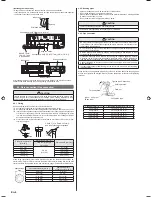
7.2. Indoor unit wiring
(1) Remove the wire cover. (Remove the 1 screw.)
(2) Remove the cable clamp. (Remove the 1 screw.)
(3) Bend the end of the connection cable as shown in the
fi
gure.
(4) Connect the end of the connection cable fully inserting into the terminal block.
(5) Fasten the connection cable with a cable clamp. (Attach the 1 screw.)
Insert the wire cover tab into the square hole
of the indoor unit and fasten with a screw.
Cable clamp
Connection
cable
Screw
Screw
Wire cover
Connection cable
Terminal block
Cable clamp
Connection
cable
Screw
Screw
Wire cover
Earth (Ground)
wire
Earth
(Ground)
screw
Indoor unit terminal block
Disconnect switch
Please connect
it to the specified
terminal.
Outdoor unit or
Branch box
• To connect the indoor unit wires to the terminal correctly, refer to the
fi
gure for proper
length.
14AWG
Earth (Ground) wire
Conduit holder
Conduit connector
25 mm
(1-13/32 in.)
140 mm
(5-1/2 in.)
25 mm
(1-13/32 in.)
160 mm
(5/16 in.)
7.3. How to the install the indoor unit wire harness
(1) Remove the screws, then remove the conduit holder.
(2) Fasten the indoor unit wire harness to the conduit holder using the lock nut.
IMPORTANT: Refer to [7.1. Wiring system diagram] about the length of indoor unit wire
harness.
(3) Use the screws to install the conduit holder provide with the indoor unit.
(4) Remove the screws, then remove the cable clamper.
(5) Connect indoor unit wire harness to the terminal.
Refer to the wiring diagram
(6) Use the screws to install the cable clamper.
Lock nut
Conduit holder
Earth (Ground) wire
Screw
Conduit connector
9319357041_IM.indb 7
9319357041_IM.indb 7
11/30/2011 1:32:49 PM
11/30/2011 1:32:49 PM
Summary of Contents for 9319357041
Page 14: ......


