background image

En-9

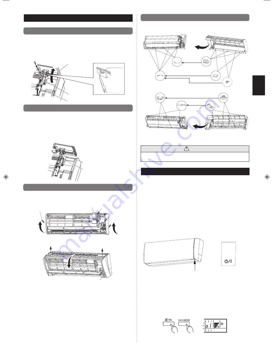
9.  FRONT PANEL REMOVAL AND INSTALLATION

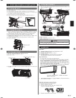
9.1. Intake grille removal

 (1)  Open the intake grille.
 (2)  While holding the intake grille, lift up the grille stay and secure the intake grille. 
 (3)  Remove the screws from the arm-cover on the top part of the front panel 

(in 2 places, one on the left and one on the right).

 (4)  Push down the arm-cover grips to release the lock.
 (5)  Open the intake grille until it is horizontal, and pull it towards you to remove it.

(1)

(2)

(3)

(4)

Intake grille

Arm-cover knob

Grille stay

Intake grille

Grille stay

9.2. Intake grille installation

 (1)  Make the intake grille horizontal and push the attachment shafts into the holes for 

them in the top of the front panel (in 2 places, one on the left and one on the right).

 (2)  While holding the intake grille, lift up the grille stay and secure the intake grille.  
 (3)  Push the arm-cover grips up, and lock the intake grille attachment shaft.
 (4)  Fix the arm-cover on the top part of the front panel using screws (in 2 places, one on 

the left and one on the right).

 (5)  Lift up the intake grille a little, and return the grille stay to its original position.
 (6)  Close the intake grille.

Attachment shaft

Hole

9.3. Front panel removal

 (1)  Remove intake grille. (Reference the intake grille removal.)
 (2)  Remove wire cover. (Remove the 1 screw.)
 (3)  Remove 4 screws.

Screws (4 position)

Wire cover Screw (Wire cover)

 (4)  The front panel is pulled to the front, raising the upper surface, and a front panel is 

removed.

Front panel

9.4. Front panel installation

(1) First, 

fi

 t the lower part of the front panel, and insert top and bottom hooks. (2 top 

sides, 7 bottom sides, 2 center)

Indoor unit

Bottom holes

(3 position)

Bottom hooks

(3 position)

Bottom holes

(4 position)

Center holes

(2 position)

Center hooks

(2 position)

Top hooks

(2 position)

Top holes

(2 position)

Indoor unit

Front panel

Bottom hooks

(2 position)

Bottom hooks
(2 position)

Front panel

(2) Attach the 4 screws.
(3) Attach the wire cover. (Attach the 1 screw.)
(4) Attach the intake grille.

 CAUTION

Install the Front panel and Intake grille securely. If installation is imperfect, the Front 
panel or Intake grille may fall off and cause injury.

10. TEST  RUN

Check items

(1)  Is operation of each button on the remote controller unit normal?

(2)  Does each lamp light normally?

(3) Do 

air

fl

 ow direction louvers operate normally?

(4)  Is the drain normal?

(5)  Do not have an abnormal noise and vibration during operation?


Do not operate the air conditioner in test run for a long time.

[Operation method]

  For the operation method, refer to the operating manual.

   The outdoor unit, may not operate, depending on the room temperature. In this case, 

keep on pressing the MANUAL AUTO button of the indoor unit for more than 10 

seconds. The OPERATION indicator lamp (green) and TIMER indicator lamp (orange) 

will begin to 

fl

 ash simultaneously during cooling test run. Then, heating test run will 

begin in about 3 minutes when HEAT is selected by the remote control operation. (Please 

follow the operating manual for remote control operation.)

(When the air conditioner is running by pressing the test run button, the OPERATION 

indicator lamp and TIMER indicator lamp will simultaneously 

fl

 ash slowly.)

Press and hold MANUAL AUTO 
button for 10 seconds

MANUAL AUTO button


When ending the test run, keep on pressing the MANUAL AUTO button of the indoor 

unit for more than 3 seconds.

[Using the wired remote controller] (Option)

For the operation method, refer to the operating manual.
(1)  Stop the air conditioner operation.
(2)  Press the MODE button and the FAN button simultaneously for 

2 seconds or more to start the test run.

Test run display

(3)  Press the start/stop button to stop the test run.

9319357041_IM.indb   9

9319357041_IM.indb   9

11/30/2011   1:32:51 PM

11/30/2011   1:32:51 PM

Summary of Contents for 9319357041

Page 1: ...çais Español INSTALLATION MANUAL MANUEL D INSTALLATION MANUAL DE INSTALACIÓN For authorized service personnel only Pour le personnel agréé uniquement Solo para personal autorizado PART NO 9319357041 AIR CONDITIONER ...

Page 2: ... runs as short as possible Use the flare method for connecting tubing Apply refrigerant lubricant to the matching surfaces of the flare and union tubes before connecting them then tighten the nut with a torque wrench for a leak free connection Check carefully for leaks before opening the refrigerant valves When Servicing Turn the power OFF at the main circuit breaker panel before opening the unit ...

Page 3: ...ket 1 Tapping screw big 5 Name and Shape Q ty Name and Shape Q ty Remote controller 1 Tapping screw small 2 Battery 2 Air cleaning filter 2 Seal A It is used when the diameter of gas pipe is Ø12 70 or more It is necessary when using AS15 1 The following items are necessary to install this air conditioner The items are not includ ed with the air conditioner and must be purchased separately Name Q t...

Page 4: ...such as storing food raising animals growing plants or preserving precision devices or art objects It can degrade the quality of the preserved or stored objects Do not install where there is the danger of combustible gas leakage Do not install the unit near a source of heat steam or flammable gas Install the unit where drainage does not cause any trouble Install the indoor unit outdoor unit branch...

Page 5: ... the outside with decorative tape For Left rear piping Left piping Interchange the drain cap and the drain hose CAUTION Insert drain hose and drain cap securely Drain should slope down to avoid water leakage When inserting be sure not to attach any material besides water If any other material is attached it will cause deterioration and water leakage After removing drain hose be sure not to forget ...

Page 6: ...an indicated in the table for flaring with R410A flare tools to achieve the specified flaring Use a thickness gauge to measure the dimension A Width across flats Pipe outside diameter mm in Width across flats of Flare nut mm in 6 35 1 4 17 21 32 9 52 3 8 22 7 8 12 70 1 2 26 1 1 32 15 88 5 8 29 1 5 32 19 05 3 4 36 1 13 32 6 9 2 Bending pipes If pipes are shaped by hand be careful not to collapse th...

Page 7: ...rminal block 5 Fasten the connection cable with a cable clamp Attach the 1 screw Insert the wire cover tab into the square hole of the indoor unit and fasten with a screw Cable clamp Connection cable Screw Screw Wire cover Connection cable Terminal block Cable clamp Connection cable Screw Screw Wire cover Earth Ground wire Earth Ground screw Indoor unit terminal block Disconnect switch Please conn...

Page 8: ...Connection cable Left piping For connection from the left rear PROHIBITED Pipe Connection pipe heat insulation Bind the pipes together so that there is no gap Indoor unit pipe heat insulation 7 4 How to connect wiring to the terminals Caution when wiring cable When stripping off the insulation of a lead wire always use a special tool such as a wire stripper If there is no special tool available ca...

Page 9: ... Center hooks 2 position Top hooks 2 position Top holes 2 position Indoor unit Front panel Bottom hooks 2 position Bottom hooks 2 position Front panel 2 Attach the 4 screws 3 Attach the wire cover Attach the 1 screw 4 Attach the intake grille CAUTION Install the Front panel and Intake grille securely If installation is imperfect the Front panel or Intake grille may fall off and cause injury 10 TES...

Page 10: ...controller holder installation Install the remote controller a maximum distance of 6 m from the remote control signal receiver However when installing the remote controller check that it operates cor rectly Install the remote controller holder to a wall pillar etc with the tapping screw Remote controller holder fixing Remote controller mounting Remote controller holder Tapping screw small 1 Set Re...

Page 11: ...ART STOP button until only the clock is displayed on the remote controller display 2 Press the MODE button for at least 5 seconds to display the current signal code initially set to 3 Press the SET TEMP buttons to change the signal code between Match the code on the display to the air conditioner signal code 4 Press the MODE button again to return to the clock display The signal code will be chang...

Page 12: ... to the installation conditions Incorrect settings can cause the indoor unit to malfunction After the power is turned on perform the FUNCTION SETTING according to the installation conditions using the remote controller The settings may be selected between the following two Function Number or Setting Value Settings will not be changed if invalid numbers or setting values are selected Refer to the i...

Page 13: ...nsor error 4 2 Indoor unit Heat Ex Middle temp sensor error 5 1 Indoor unit fan motor error 5 3 Drain pump error 5 7 Damper error 5 8 Intake grille error 5 15 Indoor unit error 6 2 Outdoor unit main PCB model information error or communication error 6 3 Inverter error 6 4 Active filter error PFC circuit er ror 6 5 Trip terminal L error 6 10 Display PCB microcomputers communication error 7 1 Discha...

Page 14: ......

Reviews: