background image

En-2

1. SAFETY PRECAUTIONS

Be sure to read this Manual thoroughly before installation.

• 

The warnings and precautions indicated in this Manual 

• 

contain important information pertaining to your safety. Be 

sure to observe them.

Hand this Manual, together with the Operating Manual, to 

• 

the customer. Request the customer to keep them on hand 

for future use, such as for relocating or repairing the unit. 

 WARNING

This mark indicates procedures which, 

if improperly performed, might lead to 

the death or serious injury of the user.

Request your dealer or a professional installer to in-

• 

stall the indoor unit in accordance with this Installation 

Manual. An improperly installed unit can cause serious 

accidents such as water leakage, electric shock, or fire. If 

the indoor unit is installed in disregard of the instructions 

in the Installation Manual, it will void the manufacturer’s 

warranty.
Do not turn ON the power until all work has been com-

• 

pleted. Turning ON the power before the work is complet-

ed can cause serious accidents such as electric shock 

or fire.

If refrigerant leaks while work is being carried out, ven-

• 

tilate the area. If the refrigerant comes in contact with a 

flame, it produces a toxic gas.

Installation work must be performed in accordance with 

• 

national wiring standards by authorized personnel only.

 CAUTION

This mark indicates procedures which, 

if improperly performed, might possibly 

result  in personal harm to the user, or 

damage to property.

2. ABOUT THE UNIT

2.1. Precautions for using R410A  

refrigerant

WARNING

Do not introduce any substance other than the prescribed 

• 

refrigerant into the refrigeration cycle. If air enters the 

refrigeration cycle, the pressure in the refrigeration cycle 

will become abnormally high and cause the piping to 

rupture.
If there is a refrigerant leak, make sure that it does 

• 

not exceed the concentration limit. If a refrigerant leak 

exceeds the concentration limit, it can lead to accidents 

such as oxygen starvation.

Do not touch refrigerant that has leaked from the refriger-

• 

ant pipe connections or other area. Touching the refriger-

ant directly can cause frostbite.
If a refrigerant leak occurs during operation, immediately 

• 

vacate the premises and thoroughly ventilate the area. If 

the refrigerant comes in contact with a flame, it produces 

a toxic gas.

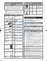
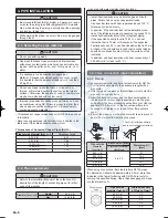
2.2. Special tools for R410A

 WARNING

To install a unit that uses R410A refrigerant, use dedi-

• 

cated tools and piping materials that have been manufac-

tured specifically for R410A use. Because the pressure 

of R410A refrigerant is approximately 1.6 times higher 

than the R22, failure to use dedicated piping material or 

improper installation can cause rupture or injury.  

Furthermore, it can cause serious accidents such as 

water leakage, electric shock, or fire.

Tool name

Changes

Gauge manifold

The pressure in the refrigerant 

system is extremely high and can

-

not be measured with a conven-

tional gauge. To prevent erroneous 

mixing of other refrigerants, the 

diameter of each port has been 

changed. It is recommended to use 

a gauge manifold with a high  

pressure display range of –0.1 to 

5.3 MPa and a low pressure dis-

play range of –0.1 to 3.8 MPa.

Charging hose

To increase pressure resistance, 

the hose material and base size 

were changed. 

(The charging port thread diameter 

for R410A is 1/2 UNF 20 threads 

per inch.)

Vacuum pump

A conventional vacuum pump can 

be used by installing a vacuum 

pump adapter. 

Be sure that the pump oil does 

not backflow into the system. Use 

one capable for vacuum suction of 

–100.7 kPa (5 torr, –755 mmHg).

Gas leakage detector

Special gas leakage detector for 

R410A refrigerant.

1125-9379122009.indd   2

2008/11/26   7:57:04

www.enindel.com

Summary of Contents for ABYA45LCT

Page 1: ...ulation 5 INSTALLING DRAIN PIPES 8 6 ELECTRICAL WIRING 9 6 1 Electrical requirement 6 2 Wiring method AIR CONDITIONER INDOOR UNIT Ceiling type PART NO 9379122009 02 7 REMOTE CONTROLLER SETTING 11 7 1 Load batteries R03 LR03 2 7 2 Remote control unit holder installation 8 FUNCTION SETTING 11 8 1 Entering the function setting mode 8 2 Function setting 9 SELECTING THE REMOTE CONTROL UNIT SIGNAL CODE ...

Page 2: ...ill become abnormally high and cause the piping to rupture If there is a refrigerant leak make sure that it does not exceed the concentration limit If a refrigerant leak exceeds the concentration limit it can lead to accidents such as oxygen starvation Do not touch refrigerant that has leaked from the refriger ant pipe connections or other area Touching the refriger ant directly can cause frostbit...

Page 3: ...bustible gas leakage Do not install the unit near a source of heat steam or flammable gas Install the indoor unit outdoor unit power supply cable transmission cable and remote control cable at least 1 m away from a television or radio receivers The purpose of this is to prevent TV reception interference or radio noise Even if they are installed more than 1 m apart you could still receive noise und...

Page 4: ...n for Suspension bolt Ceiling Wall Template Drilling position for piping 3 3 3 Location of ceiling suspension bolts 30 Suspension bolt pitch 1600 Dimensions Space Required for Installation 30 10 155 300 INDOOR UNIT TOP VIEW INDOOR UNIT Suspension bolt should extend outward 30 to 75 mm Unit mm Install the indoor unit on a place having a sufficient 1 strength so that it withstands against the weight...

Page 5: ... nut to each bolt The two special nuts are provided with the unit The M10 nut must be obtained locally Refer to the figure Bolt Strength N kgf 980 to 1470 100 to 150 Ceiling panel Special nut A Included Special nut B Included M10 Nut Obtained locally 10 to 15 Unit mm 3 3 6 Installing the indoor unit Lift unit so that suspension bolts pass through the suspen 1 sion fittings at the sides four places...

Page 6: ... that is 15 mm or thicker and if the expected humidity exceeds 80 use heat insulation that is 20 mm or thicker If heat insulation is used that is not as thick as specified condensation may form on the surface of the insulation In addition use heat insulation with heat conductivity of 0 045 W m K or less at 20 C 4 PIPE INSTALLATION CAUTION Be more careful that foreign matter oil water etc does not ...

Page 7: ...ipes are repeatedly bend or stretched the material will harden making it difficult to bend or stretch them any more Do not bend or stretch the pipes more than three times CAUTION To prevent breaking of the pipe avoid sharp bends If the pipe is bent repeatedly at the same place it will break 4 3 3 Pipe connection CAUTION Be sure to apply the pipe against the port on the indoor unit and the outdoor ...

Page 8: ...correctly within the indoor unit Indoor unit rear view VT wire Drain hose If the drain hose will not be connected to the right rear 3 piping cut the hole cover at the points indicated in Fig a and attach it to the piping hole as shown in Fig b a Cut x 5 Hole cover b 4 4 Installing heat insulation CAUTION After checking for gas leaks refer to the Installation Manual of the outdoor unit perform this...

Page 9: ...l box cover can cause serious accidents such as electric shock or fire through exposure to dust or water Install sleeves into any holes made in the walls for wiring Otherwise a short circuit could result Install a ground leakage breaker In addition install the ground leakage breaker so that the entire AC main power supply is cut off at the same time Otherwise electric shock or fire could result In...

Page 10: ...Do not attempt to recharge dry batteries Use the specified wires connect them securely and fasten 3 them so that there is no stress placed on the terminals Use an appropriate screwdriver to tighten the terminal 4 screws Do not use a screwdriver that is too small other wise the screw heads may be damaged and prevent the screws from being properly tightened Do not tighten the terminal screws too muc...

Page 11: ...control unit are replaced If you use a signal code other than signal code A reset the signal code after replacing the batteries If you do not know the air conditioner signal code setting try each of the signal codes until you find the code which operates the air conditioner NOTE Never mix new and used batteries or batteries of different types Batteries should last about one year under normal use I...

Page 12: ...FUNCTION SETTING be sure to turn off the power and turn it on again 8 2 Function setting STEP 2 Selecting the Function Number and Setting Value Press the SET TEMP 1 buttons to select the func tion number Press the MODE button to switch between the left and right digits Press the FAN button to proceed to setting the value 2 Press the FAN button again to return to the function number selection Press...

Page 13: ...ode of the remote control unit to operate only the air conditioner you wish to set four selections possible When two or more air conditioners are installed in a room please contact your retailer to set the individual air conditioner signal codes Confirm the setting of the remote control unit signal code and the printed circuit board setting If these are not confirmed the remote control unit cannot...

Page 14: ...roller abnormal 2 times 2 times Indoor room temperature sensor error 2 times 3 times Indoor heat exchanger tempera ture sensor middle error 2 times 4 times Indoor heat exchanger tempera ture sensor inlet error 2 times 6 times Float switch operated 3 times 2 times Outdoor discharge pipe tempera ture sensor error 3 times 3 times Outdoor heat exchanger temperature sensor outlet error 3 times 4 times ...

Page 15: ...t circuit address set up error 31 Master unit Slave unit set up error 32 Connected the indoor number set up error 33 P F C printed circuit board error If C0 appears in the unit number display there is a remote controller error Unit number Error code Content C0 1d Incompatible indoor unit is connected C0 1c Indoor unit remote control ler communication error 13 SPECIAL INSTALLATION METHODS CAUTION W...

Page 16: ...ndoor unit with the unit number 0 last Within 1 minute 2 When the indoor units are turned on error codes 01 and 31 will be displayed however these error codes will be deleted by setting the remote controller Therefore continue with the setting procedure Set the refrigerant circuit address Assign the same 2 number to all of the indoor units connected to an outdoor unit Refrigerant circuit address F...

Reviews: