
En-5
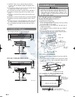
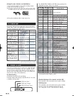
[For Half-Concealed Installation]
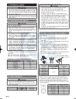
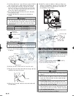
Suspension-bolt pitch should be as shown in the figure.
•
40
Ceiling Opening: 1580
40
Ceiling panel
Ceiling Opening: 640
15
Suspension bolt should
extend outward 30 to 50 mm.
INDOOR UNIT
Ceiling panel
Unit : mm
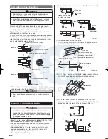
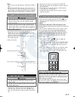
3.3.4. Select piping direction
Select connection piping and drain piping directions.
•
1 Right rear piping
5 Left piping
(Drain pipe only)
4 Left rear piping
(Drain pipe only)
2 Top piping
(Connection pipe only)
3 Right
piping
Cut off the piping outlet cutting groove
with a hacksaw, etc.
INDOOR UNIT (TOP VIEW)
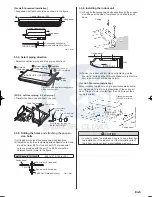
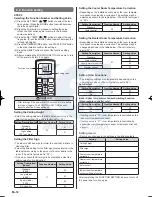
[FOR
○
4
Left rear piping,
○
5
Left piping]
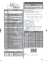
Transfer the Drain cap and Drain cap seal.
•
Drain Cap seal
Drain Cap
Indoor Unit
Drain Pan
Drain Cap Seal
Drain Cap
Push cap all the way on
(as far as it will go).
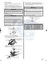
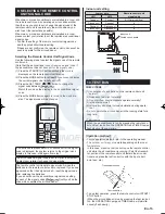
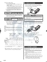
3.3.5. Drilling the holes and attaching the suspen-
sion bolts
Drill ø25 mm holes at the suspension-bolt locations.
(1)
Install the bolts, then temporarily attach Special nuts A and
(2)
B and a normal M10 nut to each bolt. (The two special
nuts are provided with the unit. The M10 nut must be
obtained locally.) Refer to the figure.
Bolt Strength [N (kgf)]
980 to 1470 (100 to 150)
Ceiling panel
Special nut A (Included)
Special nut B (Included)
M10 Nut (Obtained locally)
10 to 15
Unit : mm
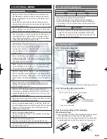
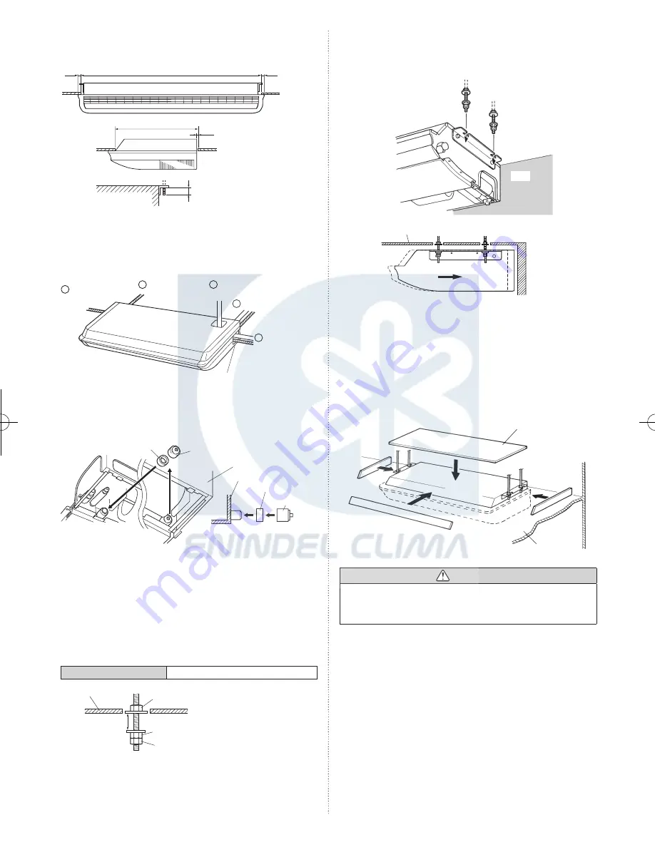
3.3.6. Installing the indoor unit
Lift unit so that suspension bolts pass through the suspen-
(1)
sion fittings at the sides (four places), and slide the unit
back.
Ceiling
INDOOR UNIT
Wall
Ceiling panel
Wall
Fasten the indoor unit into place by tightening-up the
(2)
special “B” bolts and the M10 nuts. Make sure that unit is
secure and will not shift back and forth.
[For Half-Concealed Installation]
When installing the indoor unit in a semi-concealed orienta-
tion, make sure to reinforce the insulation of the unit on all
sides. Drops of water may fall from the unit if it is not thor-
oughly insulated.
Glass wool insulate
(10 to 20 mm thick)
Wall
Ceiling panel
INDOOR UNIT
(TOP VIEW)
CAUTION
In order to check the drainage, be sure to use a level dur-
•
ing installation of the indoor unit. If the installation site of
the indoor unit is not level, water leakage may occur.
1125-9379122009.indd 5
2008/11/26 7:57:05
www.enindel.com


