En-24
]1
12.3. IR Receiver Unit (Optional parts)
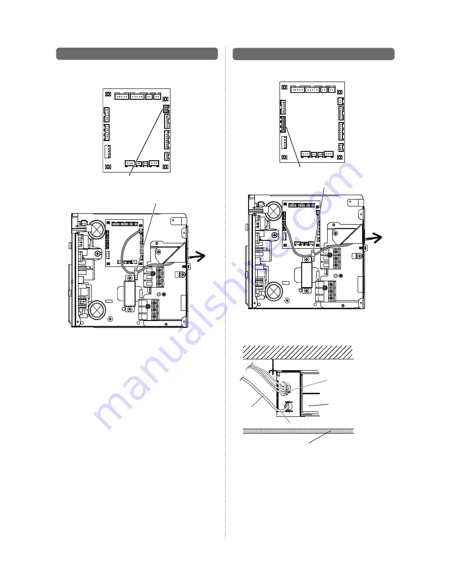
Connection method
• Connection terminals
Reciever unit terminal (CN13)
• Wiring arrangement
Binder
• Use 7 pins for receiver unit cable.
• At first, connect the receiver unit cable to the Receiver unit
terminal (CN13).
Binder
Avoid covering the air inlet
with the wiring.
Avoid touching the ceiling with the wiring
Ceiling
Power supply
cable
Do not bind the power supply cable and other cables together.
]1
12.2. Remote sensor (Optional parts)
Connection method
• Connection terminals
Remote sensor terminal (CN8)
• Wiring arrangement
Binder
• Remove the existing connector and replace it with the remote
sensor connector (ensure that the correct connector is used).
• The original connector should be insulated to ensure that it
does not come into contact with other electrical circuitry.
Setting for room temperature correction
When a remote sensor is connected, set the function setting
of indoor unit as indicated below.
• Set Function Number “30” (Cool air temperature trigger)
to “00” (Default)
• Set Function Number “31” (Hot air temperature trigger)
to “02” (Adjust(2))


