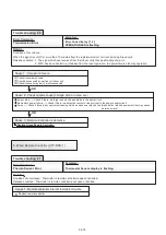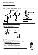
Error Contents :
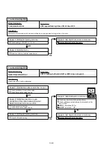
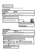
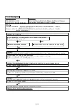
Software Error
Symptom :
Error Code display [ C A ]
All the control items do not operate.
Other Controls are left they are.
Details :
Condition of occurrence : Micon program performed an abnormal control.
Error of inside information of EEPROM.
initial setting of Network Converor PCB was not normally performed.
Release condition : Micon has been reset, and the control of Network Convertor became normal.
When error disappeared and Network Convetor becomes available to control.
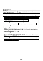
Trouble shooting 67
Trouble shooting 68
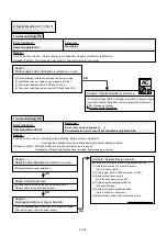
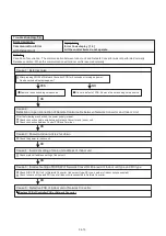
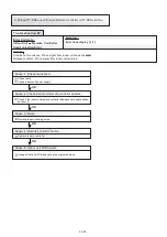
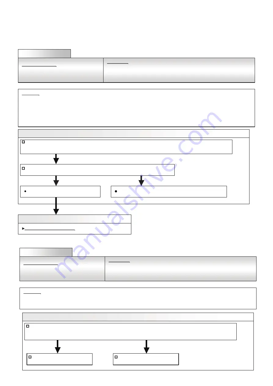
Refrigerant circuit address setting
error
Symptom :
Error Code display [ 2 6 ]
Cause 1 : Check of number of indoor unit registration refrigerant circuits
Check indoor unit registration.
(1) Number of refrigerant circuits of indoor unit registered at Replace Group Remote Controller is 3 refrigerant circuits or more
even though connected to one converter.
Make 2 refrigerant circuits or less
and wait 2 minutes
YES
NO
Replace Network Convertor
Replace Group Remote Controller
Condition of occurrence :
Indoor unit registration is 3 refrigerant circuits or more.
Release condition :
Indoor unit registration is 2 refrigerant circuits or less.
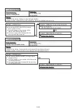
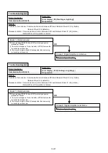
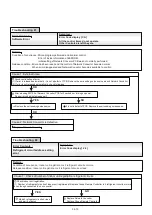
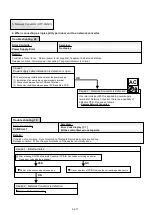
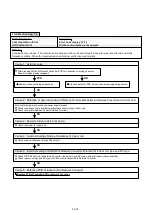
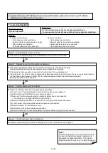
Cause 1 : External noise
Check continuation of error.
(1) If error is released automatically, it is not a defect of PCB. Remove the surrounding noise source around Network Convertor.
(2) If error is not released automatically, check followings.
After pressing SW104 of Network Convertor PCB for 5 seconds or turning on power.
Does error code display reappear?
OK
OK
It is not a defect of PCB. Remove the surrounding noise source.
Remove the surrounding noise source.
YES
NO
Cause 2 : Network Convertor is defective.
Replace Network Convertor.
04-70
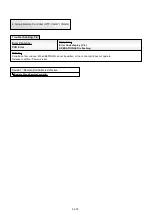
Error Contents :
Details :
Summary of Contents for Airstage J-II
Page 1: ...Small VRF system for light commercial and home use SERVICE MANUAL ...
Page 2: ......
Page 6: ......
Page 7: ...1 TEST RUN ...
Page 8: ......
Page 27: ...2 OUTDOOR UNIT OPERATION CONTROL ...
Page 28: ......
Page 42: ......
Page 43: ...3 INDOOR UNIT OPERATION ...
Page 44: ......
Page 63: ...4 TROUBLE SHOOTING ...
Page 73: ......
Page 170: ......
Page 171: ...5 APPENDING DATA UNIT ...
Page 172: ......
Page 174: ...MODELS AUXB07 AUXB09 AUXB12 AUXB14 AUXB18 AUXB24 05 02 5 2 WIRING DIAGRAM 5 2 1 Indoor Unit ...
Page 175: ...MODELS AUXD18 AUXD24 AUXA30 AUXA36 AUXA45 AUXA54 05 03 ...
Page 176: ...MODELS ARXB07 ARXB09 ARXB12 ARXB14 ARXB18 05 04 ...
Page 177: ...MODEL ARXB24 MODELS ARXB30 ARXB36 05 05 ...
Page 178: ...MODEL ARXB45 05 06 ...
Page 179: ...MODEL ARXA24 MODELS ARXA30 ARXA36 ARXA45 05 07 ...
Page 180: ...MODELS ARXC36 ARXC45 ARXC60 MODELS ARXC72 ARXC90 05 08 ...
Page 181: ...MODELS ARXD07 ARXD09 ARXD12 ARXD14 ARXD18 ARXD24 05 09 ...
Page 182: ...MODELS AB A12 AB A14 AB A18 AB A24 05 10 ...
Page 183: ...MODELS AB A12LBTH AB A14LBTH 05 11 AB A18LBTH AB A24LBTH ...
Page 184: ...05 12 MODELS AB A30 AB A36 AB A45 AB A54 ...
Page 185: ...05 13 MODELS AB A30LBTH AB A36LBTH AB A45LBTH AB A54LBTH ...
Page 186: ...MODELS AS A07 AS A09 AS A12 AS A14 05 14 ...
Page 187: ...MODELS AS E07 AS E09 AS E12 AS E14 05 15 ...
Page 188: ...MODELS AS A18 AS A24 AS A30 05 16 ...
Page 189: ...05 17 MODELS AS A18LACH AS A24LACH AS A30LACH ...
Page 190: ...05 18 MODELS AJ A36 45 54LALH 5 2 2 Outdoor Unit ...
Page 195: ...6 DISASSEMBLY PROCESS ...
Page 196: ......


