01-07
SWITCH POSITION
SW107
SW108
SW109
MODE
/EXIT
SELECT ENTER
LED101
(GREEN)
POWER
MODE
LED105
LED104
LED102
(RED)
ERROR
Push button switch
7 Segment
LED Lamp
Outdoor unit printed circuit board
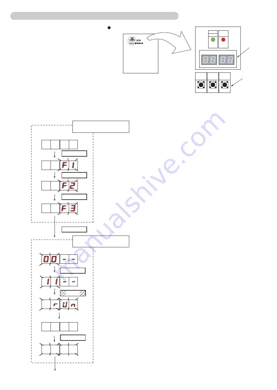
Check that the rotary switch IU AD on the indoor unit Main PCB is set to “00”.If it is not
set to “00”, it means the address of that device is not set. (Factory default is “00”).
Turn on the power of the indoor and outdoor units.
When the system is normal, nothing will be displayed on the 7 segment display.
When ERROR is displayed, inspect the units.
Use the “MODE/EXIT”, “SELECT”, and “ENTER” buttons on the outdoor unit Main PCB to configure settings according to the procedures below .
1: FUNCTION Setting
First 2 digits Last 2 digits
(the display when the
main power is turned on)
(When [F4] to [F9] are displayed,
continue to press the “SELECT”
button until [F3] is displayed.)
MODE/EXIT
SELECT
SELECT
ENTER
1-2-4 Automatic address setting for Indoor units
It may take about 10 minutes for completing
the processing.
End
First 2 digits Last 2 digits
Press the “SELECT” button until
“11” is displayed.
Press the “ENTER” button for more
than 3 seconds.
Automatic address setting
for indoor units
The number of indoor units with normal set-
tings will be displayed at the first 2 digits of
the 7 segment display. The number of indoor
units with error will be displayed at the last 2
digits.
NOTE) After the “ENTER” button is pressed, the
end processing will occur for about 30 seconds.
During this period, the 7 segment will blink.
ENTER
SELECT
ENTER
Error
Found
Summary of Contents for Airstage J-II
Page 1: ...Small VRF system for light commercial and home use SERVICE MANUAL ...
Page 2: ......
Page 6: ......
Page 7: ...1 TEST RUN ...
Page 8: ......
Page 27: ...2 OUTDOOR UNIT OPERATION CONTROL ...
Page 28: ......
Page 42: ......
Page 43: ...3 INDOOR UNIT OPERATION ...
Page 44: ......
Page 63: ...4 TROUBLE SHOOTING ...
Page 73: ......
Page 170: ......
Page 171: ...5 APPENDING DATA UNIT ...
Page 172: ......
Page 174: ...MODELS AUXB07 AUXB09 AUXB12 AUXB14 AUXB18 AUXB24 05 02 5 2 WIRING DIAGRAM 5 2 1 Indoor Unit ...
Page 175: ...MODELS AUXD18 AUXD24 AUXA30 AUXA36 AUXA45 AUXA54 05 03 ...
Page 176: ...MODELS ARXB07 ARXB09 ARXB12 ARXB14 ARXB18 05 04 ...
Page 177: ...MODEL ARXB24 MODELS ARXB30 ARXB36 05 05 ...
Page 178: ...MODEL ARXB45 05 06 ...
Page 179: ...MODEL ARXA24 MODELS ARXA30 ARXA36 ARXA45 05 07 ...
Page 180: ...MODELS ARXC36 ARXC45 ARXC60 MODELS ARXC72 ARXC90 05 08 ...
Page 181: ...MODELS ARXD07 ARXD09 ARXD12 ARXD14 ARXD18 ARXD24 05 09 ...
Page 182: ...MODELS AB A12 AB A14 AB A18 AB A24 05 10 ...
Page 183: ...MODELS AB A12LBTH AB A14LBTH 05 11 AB A18LBTH AB A24LBTH ...
Page 184: ...05 12 MODELS AB A30 AB A36 AB A45 AB A54 ...
Page 185: ...05 13 MODELS AB A30LBTH AB A36LBTH AB A45LBTH AB A54LBTH ...
Page 186: ...MODELS AS A07 AS A09 AS A12 AS A14 05 14 ...
Page 187: ...MODELS AS E07 AS E09 AS E12 AS E14 05 15 ...
Page 188: ...MODELS AS A18 AS A24 AS A30 05 16 ...
Page 189: ...05 17 MODELS AS A18LACH AS A24LACH AS A30LACH ...
Page 190: ...05 18 MODELS AJ A36 45 54LALH 5 2 2 Outdoor Unit ...
Page 195: ...6 DISASSEMBLY PROCESS ...
Page 196: ......


