01-08
SWITCH POSITION
SW107
SW108
SW109
MODE
/EXIT
SELECT ENTER
LED101
(GREEN)
POWER
MODE
LED105
LED104
LED102
(RED)
ERROR
Push button switch
7 Segment
LED Lamp
Outdoor unit printed circuit board
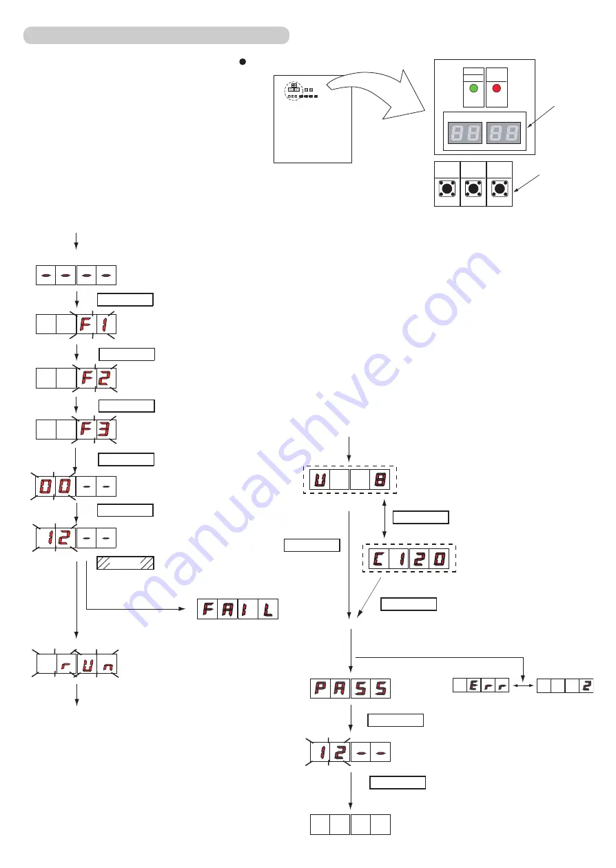
1-2-5 Indoor unit connection check
Please perform the indoor unit connection check according to following procedures.
MODE/EXIT
SELECT
SELECT
SELECT
ENTER
LED105
LED104
ENTER
Set to Function mode [F3].
(When [F4] to [F9] are displayed,
continue to press the “SELECT”
button until [F3] is displayed.)
Press the “SELECT” button until
“12” is displayed.
When indoor unit connection check
can not be performed
Turn on the power
•
of indoor unit and
outdoor unit.
Press the
•
“ENTER”
button for
more than 3 seconds.
This will be displayed when the
•
Indoor unit connection check
starts.
MODE/EXIT
SELECT
ENTER
ENTER
ENTER
(*1)
(*2)
(*1) The number of connected
indoor units
(*2) Volume ratio of the indoor
units connection
Ex.) When 8 units are connected
Ex.) When the ratio is 120%
Please refer to the following “Error code”
for details
[ Note ] Error code
22.1: Connecting Indoor units capacity error
24.2: Connecting number of indoor unit error
26.1: Dual address number is existing
Other Error code: Refer to the Trouble shooting
When it finishes normally, nothing will be displayed on
7 segment display.
When error occurs
Confirm the number of connected indoor
•
units and the volume ratio of the indoor
units connection.
Exit indoor unit connection check
•
mode.
Summary of Contents for Airstage J-II
Page 1: ...Small VRF system for light commercial and home use SERVICE MANUAL ...
Page 2: ......
Page 6: ......
Page 7: ...1 TEST RUN ...
Page 8: ......
Page 27: ...2 OUTDOOR UNIT OPERATION CONTROL ...
Page 28: ......
Page 42: ......
Page 43: ...3 INDOOR UNIT OPERATION ...
Page 44: ......
Page 63: ...4 TROUBLE SHOOTING ...
Page 73: ......
Page 170: ......
Page 171: ...5 APPENDING DATA UNIT ...
Page 172: ......
Page 174: ...MODELS AUXB07 AUXB09 AUXB12 AUXB14 AUXB18 AUXB24 05 02 5 2 WIRING DIAGRAM 5 2 1 Indoor Unit ...
Page 175: ...MODELS AUXD18 AUXD24 AUXA30 AUXA36 AUXA45 AUXA54 05 03 ...
Page 176: ...MODELS ARXB07 ARXB09 ARXB12 ARXB14 ARXB18 05 04 ...
Page 177: ...MODEL ARXB24 MODELS ARXB30 ARXB36 05 05 ...
Page 178: ...MODEL ARXB45 05 06 ...
Page 179: ...MODEL ARXA24 MODELS ARXA30 ARXA36 ARXA45 05 07 ...
Page 180: ...MODELS ARXC36 ARXC45 ARXC60 MODELS ARXC72 ARXC90 05 08 ...
Page 181: ...MODELS ARXD07 ARXD09 ARXD12 ARXD14 ARXD18 ARXD24 05 09 ...
Page 182: ...MODELS AB A12 AB A14 AB A18 AB A24 05 10 ...
Page 183: ...MODELS AB A12LBTH AB A14LBTH 05 11 AB A18LBTH AB A24LBTH ...
Page 184: ...05 12 MODELS AB A30 AB A36 AB A45 AB A54 ...
Page 185: ...05 13 MODELS AB A30LBTH AB A36LBTH AB A45LBTH AB A54LBTH ...
Page 186: ...MODELS AS A07 AS A09 AS A12 AS A14 05 14 ...
Page 187: ...MODELS AS E07 AS E09 AS E12 AS E14 05 15 ...
Page 188: ...MODELS AS A18 AS A24 AS A30 05 16 ...
Page 189: ...05 17 MODELS AS A18LACH AS A24LACH AS A30LACH ...
Page 190: ...05 18 MODELS AJ A36 45 54LALH 5 2 2 Outdoor Unit ...
Page 195: ...6 DISASSEMBLY PROCESS ...
Page 196: ......


