06-12
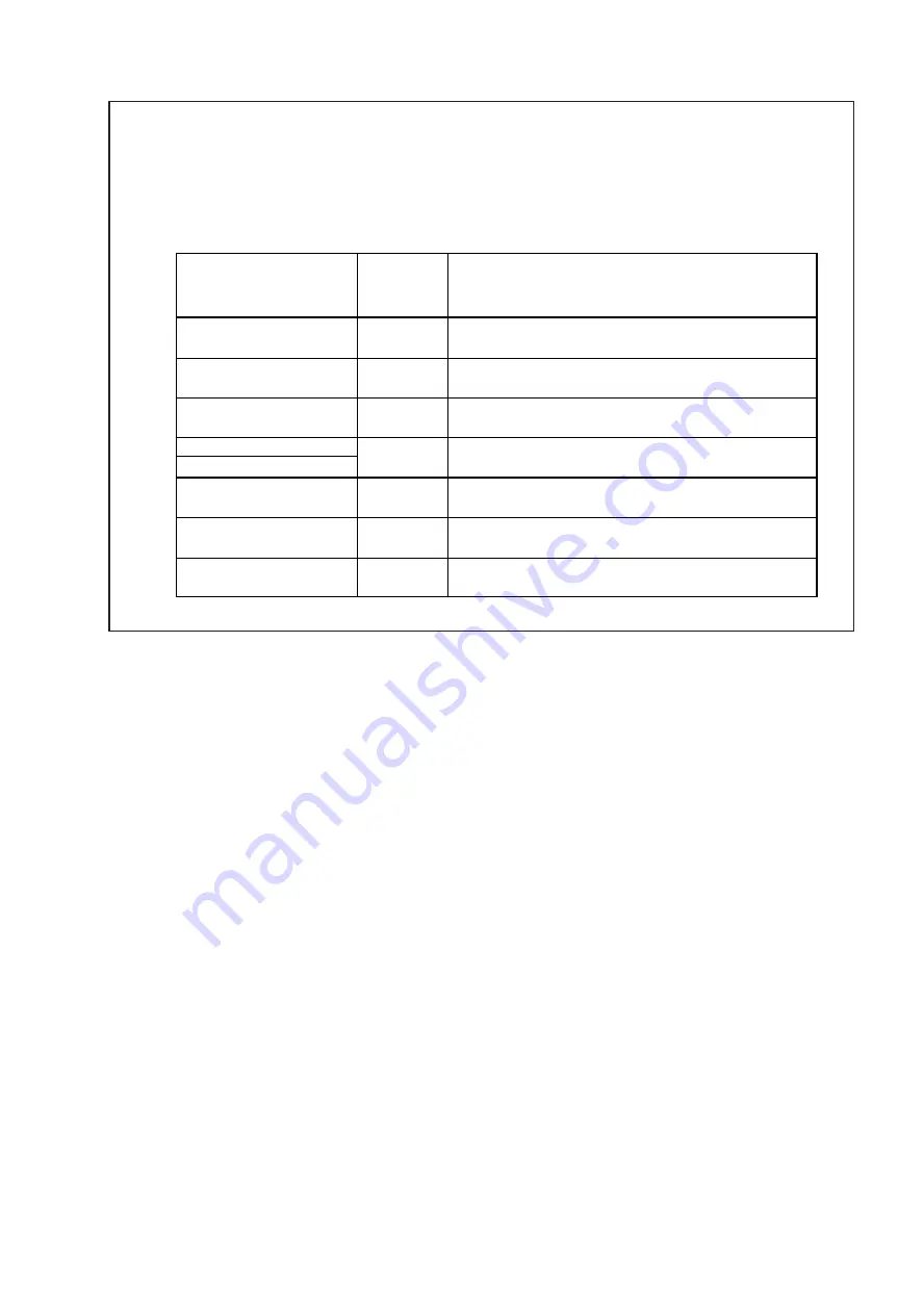
17. Precautions for exchange of refrigerant-cycle-parts
EXPANSION VALVE
4WAY VALVE
3WAY VALVE (GAS)
PRESSURE SENSOR
3WAY VALVE (LIQUID)
(1) During exchange the following parts shall be protected by wet rag and not make the allowable temperature or more.
(2) Remove the heat insulation when there is the heat insulation near the welding place.
Move and cool it when its detaching is difficult.
(3) Cool the parts when there are parts where heat might be transmitted besides the replacement part.
(4) Interrupt the flame with the fire-retardant board when the flame seems to hit the following parts directly.
(5) Do not allow moisture or debris to get inside refrigerant pipes during work.
(6) When brazing, be sure to replace the air in the pipe with nitrogen gas to prevent forming oxidization scale.
(7) Open the 3WAY VALVE because there is a possibility of squirting the refrigerant from the heated pipes at brazing.
Part name
Allowable
temperature
Precautions in work
Remove the coil before brazing.
And install the coil after brazing.
Remove the coil before brazing.
And install the coil after brazing.
Tighten the flare part gripping it. (Tightening torque :15 1.5N m)
Do the static electricity measures.
120°C
SOLENOID VALVE
Remove the coil before brazing.
And install the coil after brazing.
120°C
120°C
100°C
UNION JOINT
Remove the pressure sensor before brazing.
And install the pressure sensor after brazing.
Remove the wiring before brazing.
And connect the wire after brazing.
100°C
100°C
PRESSURE SWITCH
100°C
+-
.
Summary of Contents for Airstage J-II
Page 1: ...Small VRF system for light commercial and home use SERVICE MANUAL ...
Page 2: ......
Page 6: ......
Page 7: ...1 TEST RUN ...
Page 8: ......
Page 27: ...2 OUTDOOR UNIT OPERATION CONTROL ...
Page 28: ......
Page 42: ......
Page 43: ...3 INDOOR UNIT OPERATION ...
Page 44: ......
Page 63: ...4 TROUBLE SHOOTING ...
Page 73: ......
Page 170: ......
Page 171: ...5 APPENDING DATA UNIT ...
Page 172: ......
Page 174: ...MODELS AUXB07 AUXB09 AUXB12 AUXB14 AUXB18 AUXB24 05 02 5 2 WIRING DIAGRAM 5 2 1 Indoor Unit ...
Page 175: ...MODELS AUXD18 AUXD24 AUXA30 AUXA36 AUXA45 AUXA54 05 03 ...
Page 176: ...MODELS ARXB07 ARXB09 ARXB12 ARXB14 ARXB18 05 04 ...
Page 177: ...MODEL ARXB24 MODELS ARXB30 ARXB36 05 05 ...
Page 178: ...MODEL ARXB45 05 06 ...
Page 179: ...MODEL ARXA24 MODELS ARXA30 ARXA36 ARXA45 05 07 ...
Page 180: ...MODELS ARXC36 ARXC45 ARXC60 MODELS ARXC72 ARXC90 05 08 ...
Page 181: ...MODELS ARXD07 ARXD09 ARXD12 ARXD14 ARXD18 ARXD24 05 09 ...
Page 182: ...MODELS AB A12 AB A14 AB A18 AB A24 05 10 ...
Page 183: ...MODELS AB A12LBTH AB A14LBTH 05 11 AB A18LBTH AB A24LBTH ...
Page 184: ...05 12 MODELS AB A30 AB A36 AB A45 AB A54 ...
Page 185: ...05 13 MODELS AB A30LBTH AB A36LBTH AB A45LBTH AB A54LBTH ...
Page 186: ...MODELS AS A07 AS A09 AS A12 AS A14 05 14 ...
Page 187: ...MODELS AS E07 AS E09 AS E12 AS E14 05 15 ...
Page 188: ...MODELS AS A18 AS A24 AS A30 05 16 ...
Page 189: ...05 17 MODELS AS A18LACH AS A24LACH AS A30LACH ...
Page 190: ...05 18 MODELS AJ A36 45 54LALH 5 2 2 Outdoor Unit ...
Page 195: ...6 DISASSEMBLY PROCESS ...
Page 196: ......


