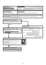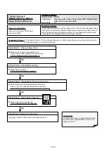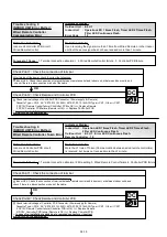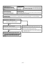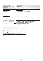
Trouble shooting 11
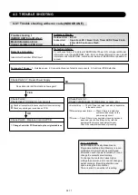
INDOOR UNIT Error Method:
Network Communication Error
Indicate or Display:
Indoor Unit : Operation LED 1 times Flash, Timer LED 4 Times Flash,
Filter LED Continuous Flash.
Outdoor Unit : E.5 U.1
Error Code : 1 4
Detective Actuators:
Indoor unit Controller PCB circuit
Indoor unit Communication PCB
Detective details:
When the cut-off of network communication is detected (more than 90 seconds
passed since the last receipt of Outdoor unit signal).
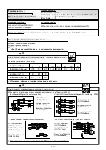
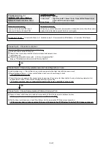
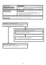
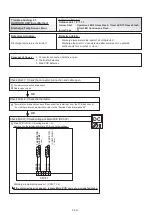
Check Point 2 : Check if any outside cause such as voltage drop or noise
Instant voltage drop ----- Check if there is any electric equipment with a large load within the same circuit.
Momentary power failure ----- Check contact failure or leak current in power supply circuit
>>Check Outdoor Unit as well.
Check if there is any equipment that causes harmonic wave near the power cable (Neon light bulb or any electronic equipment which
causes harmonic wave). And check the complete insulation of grounding.
>>If the same symptom does not reappear after resetting the power, possibility of noise is high.
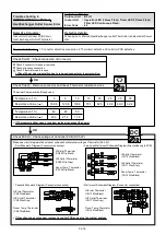
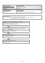
Check Point 1 : Check the connection
After turning off the power, check and correct followings.
Is Indoor Communication PCB loose?
Check loose or removed connection of communication line between Indoor
and Outdoor unit.
When the signal amplifier is connected , is it failure of signal amplifier?
(Refer to "TROUBLE SHOOTING FOR OPTIONAL PARTS")
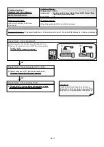
Check Point 3 : Check Communication PCB and Controller PCB
If some of Indoor units have errors, replace Communication PCB of the Indoor units that have the error.
>>If the symptom does not change, replace Indoor unit Controller PCB.
If all the Indoor units have error, check if the Outdoor Unit Communication PCB has a loose connection.
>>If the symptom does not change, replace Outdoor unit Communication PCB (Replace Controller PCB if it does not change).
OK
OK
Forecast of Cause :
1. Connection failure 2. Outside cause 3. Communication PCB failure 4. Controller PCB failure
04-21
Summary of Contents for Airstage J-II
Page 1: ...Small VRF system for light commercial and home use SERVICE MANUAL ...
Page 2: ......
Page 6: ......
Page 7: ...1 TEST RUN ...
Page 8: ......
Page 27: ...2 OUTDOOR UNIT OPERATION CONTROL ...
Page 28: ......
Page 42: ......
Page 43: ...3 INDOOR UNIT OPERATION ...
Page 44: ......
Page 63: ...4 TROUBLE SHOOTING ...
Page 73: ......
Page 170: ......
Page 171: ...5 APPENDING DATA UNIT ...
Page 172: ......
Page 174: ...MODELS AUXB07 AUXB09 AUXB12 AUXB14 AUXB18 AUXB24 05 02 5 2 WIRING DIAGRAM 5 2 1 Indoor Unit ...
Page 175: ...MODELS AUXD18 AUXD24 AUXA30 AUXA36 AUXA45 AUXA54 05 03 ...
Page 176: ...MODELS ARXB07 ARXB09 ARXB12 ARXB14 ARXB18 05 04 ...
Page 177: ...MODEL ARXB24 MODELS ARXB30 ARXB36 05 05 ...
Page 178: ...MODEL ARXB45 05 06 ...
Page 179: ...MODEL ARXA24 MODELS ARXA30 ARXA36 ARXA45 05 07 ...
Page 180: ...MODELS ARXC36 ARXC45 ARXC60 MODELS ARXC72 ARXC90 05 08 ...
Page 181: ...MODELS ARXD07 ARXD09 ARXD12 ARXD14 ARXD18 ARXD24 05 09 ...
Page 182: ...MODELS AB A12 AB A14 AB A18 AB A24 05 10 ...
Page 183: ...MODELS AB A12LBTH AB A14LBTH 05 11 AB A18LBTH AB A24LBTH ...
Page 184: ...05 12 MODELS AB A30 AB A36 AB A45 AB A54 ...
Page 185: ...05 13 MODELS AB A30LBTH AB A36LBTH AB A45LBTH AB A54LBTH ...
Page 186: ...MODELS AS A07 AS A09 AS A12 AS A14 05 14 ...
Page 187: ...MODELS AS E07 AS E09 AS E12 AS E14 05 15 ...
Page 188: ...MODELS AS A18 AS A24 AS A30 05 16 ...
Page 189: ...05 17 MODELS AS A18LACH AS A24LACH AS A30LACH ...
Page 190: ...05 18 MODELS AJ A36 45 54LALH 5 2 2 Outdoor Unit ...
Page 195: ...6 DISASSEMBLY PROCESS ...
Page 196: ......

