
En-1
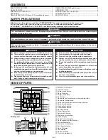
C
F
6
7
8
9
0
A
B
D
E
5
4
3
2
1
G
K
P
NM
O
J
H
L
I
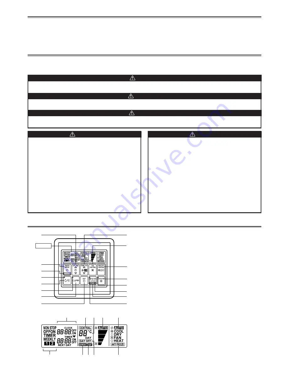
1
START/STOP button
2
Operation lamp
3
Energy save button
4
Day off button
5
Energy save lamp
6
Set button
7
Horizontal airflow direction and swing button
8
Horizontal swing lamp
9
Vertical airflow direction and swing button
0
Vertical swing lamp
A
Clock adjust button
B
Timer mode button
C
Set time button
D
Temp./Day button
E
Fan control button
F
Master control button
G
Clock display
H
Central control display
I
Set temperature/Day display
J
Fan speed display
K
Master control display
L
Anti freeze display
M
Day off display
N
Test display
O
Defrost display
P
Timer mode display
SAFETY PRECAUTIONS
●
Before using the appliance, read these “PRECAUTIONS” thoroughly and operate in the correct way.
●
The instructions in this section all relate to safety; be sure to maintain save operating conditions.
●
“DANGER”, “WARNING” and “CAUTION” have the following meanings in these instructions:
CONTENTS
NAME OF PARTS
Display panel
SAFETY PRECAUTIONS .......................................................... 1
NAME OF PARTS ..................................................................... 1
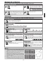
PREPARATORY OPERATION ................................................... 2
OPERATION ............................................................................. 2
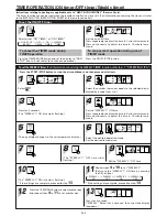
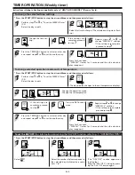
TIMER OPERATION (ON timer/OFF timer/Weekly timer) ..... 3
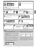
TIMER OPERATION (Weekly timer) ........................................ 5
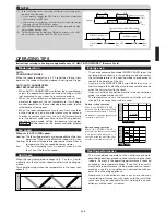
OPERATING TIPS ..................................................................... 6
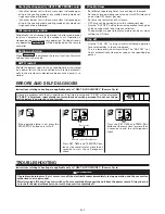
ERRORS AND SELF-DIAGNOSIS ........................................... 7
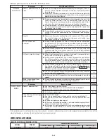
TROUBLESHOOTING .............................................................. 7
SPECIFICATIONS ..................................................................... 8
DANGER!
This mark indicates procedures which, if improperly performed, are most likely to result in the death of or serious injury to
the user or service personnel.
This mark indicates procedures which, if improperly performed, might possibly result in personal harm to the user, or
damage to property.
This mark indicates procedures which, if improperly performed, might lead to the death or serious injury of the user.
DANGER!
●
Do not attempt to install this controller by yourself.
●
This controller contains no user-serviceable parts. Al-
ways consult authorized service personnel for repairs.
●
When moving, consult authorized service personnel
for disconnection and installation of the controller.
●
If a problem (burning smell, etc.) occurs, turn off the
electrical breaker immediately to stop operation, and
then consult authorized service personnel.
●
In the event of a malfunction (burning smell, etc.), im-
mediately stop operation, turn off the electrical breaker,
and consult authorized service personnel.
●
If the wiring cord is damaged, contact your service rep-
resentative for instruction.
●
Never place fingers or foreign objects inside the outlet
port. Doing so could cause personal injury.
CAUTION!
●
Do not expose the controller directly to water.
●
Do not operate the controller with wet hands.
●
Do not touch the switches with sharp objects.
●
Always turn off the electrical breaker whenever clean-
ing the controller, the air conditioner or the air filter.
●
Check the condition of the installation stand for dam-
age.
●
Ensure that any electronic equipment is at least one
metre away from the controller.
●
Avoid installing the controller near a fireplace or other
heating apparatus.
●
When installing the controller, take precautions to pre-
vent access to infants.
●
Do not use inflammable gases near the controller.
WARNING!
CAUTION!
Display


