background image

En-3

Tapping screw A 
(Ø4×10)

6

For suspending the RB unit from 
ceiling

Tapping screw B 
(Ø4×25)

4

For suspending the RB unit from 
wall

Cable tie

2

For mounting the transmission 
cable

Cable clamp

1

For mounting the cable

Reducer type [in (mm)]

UTP-

RU01AH

UTP-

RU01BH

UTP-

RU01CH

Reducer-A

a

b

a: 3/8 (9.52) [O.D.]

b: 1/2 (12.7) [I.D.]

4

Reducer-B

a

b

a: 1/2 (12.7) [O.D.]

b: 5/8 (15.88) [I.D.]

2

1

Reducer-C

a

b

a: 1/2 (12.7) [O.D.]

b: 3/8 (9.52) [I.D.]

1

Reducer-D

a

b

a: 3/4 (19.05) [O.D.]

b: 7/8 (22.22) [I.D.]

2

Reducer-E

a

b

с

a: 3/4 (19.05) [O.D.]
b: 1/2 (12.7) [I.D.]

c: 5/8 (15.88) [I.D.]

2

Reducer-F

a

b

a: 3/4 (19.05) [O.D.]

b: 5/8 (15.88) [I.D.]

1

2.4.   Optional parts

The following optional parts are available.

Description

Model No.

Application

External connect kit

UTY-XWZXZ6

For external input
(Dry contact terminal / CNA01)

UTY-XWZXZB

For external input
(Apply voltage terminal / CNA02)

2.5.   About unit of the length

All Fujitsu General products are manufactured to metric units and tolerances. United 
States customary units are provided for reference only.
In cases where exact dimensions and tolerances are required, always refer to metric 
units.

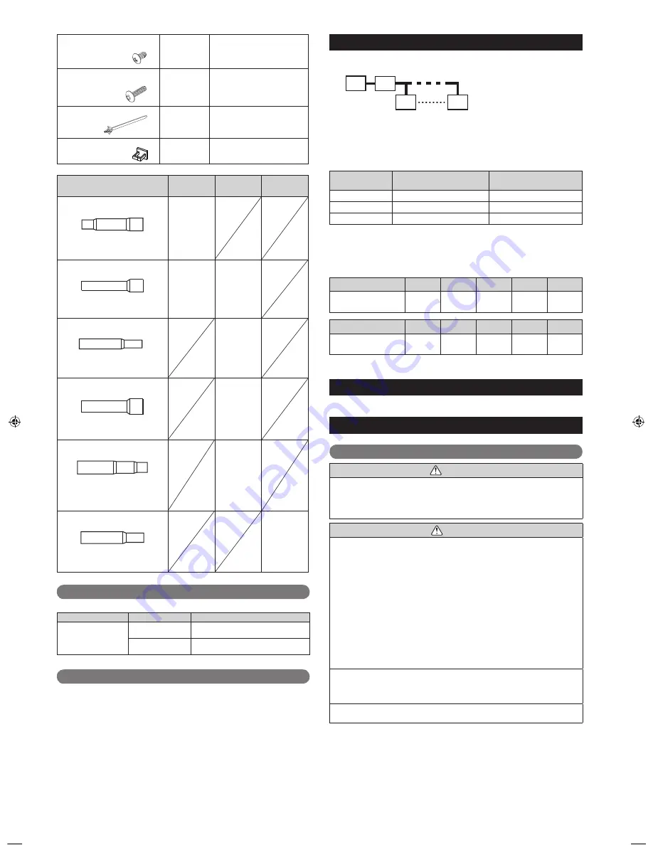
3. PRODUCT SELECTION

•  Select the RB unit to 

fi

 t the total capacity and number of the indoor units to be con-

nected downstream. (Refer to Tables 1 and 2)

I.U.=Indoor unit
RB=RB unit
O.U.=Outdoor unit

O.U.

RB

I.U.

I.U.

Calculation example: If the connected indoor units model code is 07, 09, 12 and 18.
 Q1= 

7,500 Btu/h + 9,500 Btu/h + 12,000 Btu/h +
18,000 Btu/h=47,000 Btu/h


 Select “UTP-RU01BH”

Table 1)  Conditions in which connection is possible

Model Name

Indoor unit capacity

Maximum number of con-

nectable indoor units

UTP-RU01AH

7,500 

 Q1 

 27,000 Btu/h

Up to 3 units

UTP-RU01BH

7,500 

 Q1 

 60,000 Btu/h

Up to 8 units

UTP-RU01CH

7,500 

 Q1 

 96,000 Btu/h

Up to 8 units

*  Indoor units connected downstream of the RB unit can operate all in the same operat-

ing mode. Indoor units within the same RB group cannot simultaneously operate heat-
ing and cooling.

Table 2)  Indoor unit model codes and model selection capacity

Model code

07

09

12

14

18

Indoor unit capacity 

[Btu/h]

7,500

9,500

12,000

14,000

18,000

Model code

24

30

36

48

60

Indoor unit capacity 

[Btu/h]

24,000

30,000

36,000

48,000

60,000

•  For connectable indoor units, refer to the catalogue or the Design & Technical manual.

4. PIPING SPECIFICATIONS

For details of piping speci

fi

 cations, refer to the outdoor unit installation manual.

5. INSTALLATION WORK

5.1.  Selecting an installation location

 WARNING

Take into consideration whether the place you install the main unit can fully with-
stand its weight.
For hanger bolts, use embedded inserts or embedded foundation bolts in the case 
of new installation, and use a hole-in-anchor if already installed, and attach in a 
way so that the unit’s weight can be supported.

 CAUTION

Do not install this unit in the following areas:
•  Area with high salt content, such as at the seaside. It will deteriorate metal parts, 

causing the parts to fail or the unit to leak water.

• Area 

fi

 lled with mineral oil or containing a large amount of splashed oil or steam, 

such as a kitchen. It will deteriorate plastic parts, causing the parts to fail or the unit 
to leak water.

•  Area that generates substances that adversely affect the equipment, such as sulfu-

ric gas, chlorine gas, acid, or alkali. It will cause the copper pipes and brazed joints 
to corrode, which can cause refrigerant leakage.

•  Area containing equipment that generates electromagnetic interference. It will cause 

the control system to malfunction, preventing the unit from operating normally.

•  Area that can cause combustible gas to leak, contains suspended carbon 

fi

 bers or 

fl

 ammable dust, or volatile in

fl

 ammables such as paint thinner or gasoline. If gas 

leaks and settles around the unit, it can cause a 

fi

 re.

•  Area where small animals may live. It may cause failure, smoke or 

fi

 re if small 

animals enter and touch internal electrical parts.

•  Area where animals may urinate on the unit or ammonia may be generated.

Install this unit, power supply cable and transmission cable at least 40 in (1 m) 
away from a television or radio receivers. The purpose of this is to prevent TV 
reception interference or radio noise. (Even if they are installed more than 40 in (1 m) 
apart, you could still receive noise under some signal conditions.)

If children under 10 years old may approach the unit, take preventive measures so 
that they cannot reach the unit.

Select the place to install the product after taking into consideration the following condi-
tions, and after obtaining approval from the customer.
•  Install this unit in a location that has strong support and no vibrations.
•  Install in a location that has enough space for this unit installation.
•  Install in a well-ventilated area.
•  Install in a location that is not exposed to high temperatures or humidity over a long 

periods.

•  Do not install the unit near a bedroom. Refrigerant noise may be heard from the pip-

ing.

9366249030-05_IM.indb   Sec1:3

9366249030-05_IM.indb   Sec1:3

2015/2/26   13:11:33

2015/2/26   13:11:33

Summary of Contents for Airstage UTP-RU01AH

Page 1: ...tage Parts for the Fujitsu LonWorks cables are the following Cable Type Pairs Details Catalog Number Level 4 NEMA 22AWG 1 250ft LonWorks Shielded cable K00250LW 1 500ft LonWorks Shielded cable K00500LW This addendum information shall supersede any LonWorks cable requirements listed in any of the Airstage Design Technical Manuals or Installation Manuals Design Technical Manual for Airstage V II 208...

Page 2: ...service personnel only TM Français Español MANUEL D INSTALLATION MANUAL DE INSTALACIÓN UNITÉ DE DÉRIVATION DE RÉFRIGÉRANT UNIDAD DE DERIVACIÓN DE REFRIGERANTE Pour le personnel agréé uniquement Únicamente para personal de servicio autorizado UTP RU01AH UTP RU01BH UTP RU01CH ...

Page 3: ... and floors In an Area with High Winds Securely anchor the outdoor unit down with bolts and a metal frame Provide a suitable air baffle In a Snowy Area for Heat Pump type Systems Install the outdoor unit on a raised platform that is higher than drifting snow When Connecting Refrigerant Tubing Keep all tubing runs as short as possible Use the flare method for connecting tubing Apply refrigerant lub...

Page 4: ...t breaker operating on all wires with a distance between contact of 1 8 in 3 mm for this unit The unit must be correctly grounded and the supply line must be equipped with a dif ferential breaker in order to protect the persons The units are not explosion proof and therefore should not be installed in explosive atmosphere Do not turn on the power until all installation work is complete This unit c...

Page 5: ...nstallation manual 5 INSTALLATION WORK 5 1 Selecting an installation location WARNING Take into consideration whether the place you install the main unit can fully with stand its weight For hanger bolts use embedded inserts or embedded foundation bolts in the case of new installation and use a hole in anchor if already installed and attach in a way so that the unit s weight can be supported CAUTIO...

Page 6: ...unit side Product mass lbs kg UTP RU01AH 15 7 UTP RU01BH 17 7 5 UTP RU01CH 18 8 A A B B C C 20 500 or more 20 500 or more 1 20 or more 1 20 or more Ceiling hanging Installation limit Unit in mm 5 2 2 Wall hanging 13 1 8 333 11 16 18 9 16 15 7 13 16 198 10 9 16 268 198 7 13 16 7 1 4 Unit in mm service space grille 1 20 or more Installation limit 1 20 or more 12 300 or more E g If installing a duct ...

Page 7: ...s 1 1 1 2 4 4 5 5 5 5 3 Cover B Cover A Control box Control box cover Cable clamp 6 8 9 10 11 11 8 8 10 10 10 8 7 Cable clamp Accessory Cover B Cover A Control box Control box cover 6 Change the control box attachment position 7 Attach the cable clamp accessory Thereafter put the cable in the cable clamp 8 Fix the control box position 4 screws 9 Attach Cover B to Cover A 1 screw 10 Attach Cover A ...

Page 8: ...ndoor unit capacity Btu h Suction gas pipe in mm Discharge gas pipe in mm Gas pipe in mm 7 500 9 500 12 000 14 000 1 2 12 7 Reducer 3 8 9 52 Reducer 1 2 12 7 Reducer 18 000 24 000 30 000 5 8 15 88 Reducer 1 2 12 7 5 8 15 88 Reducer 36 000 48 000 3 4 19 05 1 2 12 7 3 4 19 05 60 000 3 4 19 05 5 8 15 88 Reducer 3 4 19 05 Table 3 Connection pipe selection for when 2 to 8 indoor units are connected Tot...

Page 9: ...ns for electrical wiring WARNING Electrical work must be performed in accordance with this Manual by a person certified under the national or regional regulations Be sure to use a dedicated circuit for the unit An insufficient power supply circuit or improperly performed electrical work can cause serious accidents such as electric shock or fire Before starting work check that power is not being su...

Page 10: ...river to tighten the terminal screws Do not use a screwdriver that is too small otherwise the screw heads may be damaged and prevent the screws from being properly tightened 4 Do not tighten the terminal screws too much otherwise the screws may break 5 See the table for the terminal screw tightening torques 6 Please do not fix 2 power supply cables with 1 screw Strip 1 in 25 mm Screw with special ...

Page 11: ...rcuit Breaker MAX CKT BKR Disconnect switch shall be installed between RB unit and pull box The transmission cable connects indoor units belonging to the same RB group The transmission cable cannot be used to connect indoor units belonging to different RB groups GOOD PROHIBITED Refrigerant pipe RB group 1 RB group 1 RB group 2 RB group 2 Transmission line Transmission line Crossover wiring of powe...

Page 12: ...etting 1 RB unit address When connecting multiple RB units to 1 refrigerant system set the address at RB AD SW Rotary switch RB AD 1 Factory setting 0 Rotary switch RB AD 10 Factory setting 0 2 Refrigerant circuit address In the case of multiple refrigerant systems set REF AD SW for each refrigerant system Set to the same refrigerant circuit address as the outdoor unit Rotary switch REF AD 1 Facto...

Page 13: ...ing 24V across pins 1 3 c The allowable current is DC 5mA to 10 mA Recommended DC 5mA Provide a load resistance such that the current becomes DC 10mA or less Select very low current use contacts usable at DC 12V DC 1mA or less d The polarity is for pin 1 and for pin 3 Connect correctly When connected to Apply voltage terminals of multiple RB units with a connected unit be sure to make a branch out...

Page 14: ...er is turned on Lit Lit The wiring is incorrect The IN U terminal of RB unit and outdoor unit transmission terminal are connected with the transmission cable Correctly connect the wiring When re wiring you must turn off the power Lit Flashing There is a fault with the communication board or the main board 0 1s ON 0 1s OFF ...

Reviews: