background image

En-5

Hanger × 2 
(Accessories)

Tapping screw A × 4 

(Accessories)

(2) If hung on a wall

5.6.  Changing the positioning of the control box

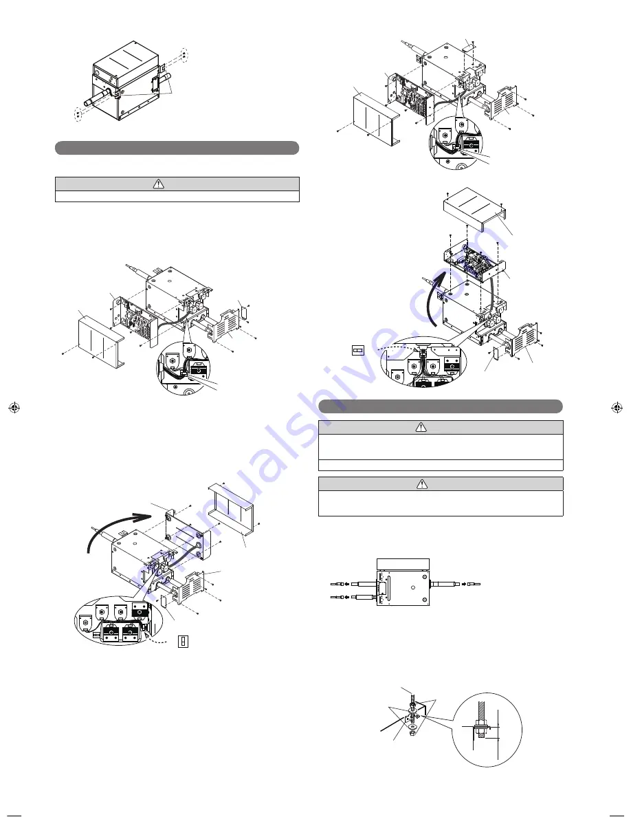
5.6.1.  Attaching to the opposite horizontal face

 CAUTION

Change the positioning of the control box on-site before performing the installation.

Change the control box attachment side as required.

(1)  Remove Cover-A.  (4 screws)
(2)  Remove Cover-B.  (1 screw)
(3)  Remove the cable from the cable clamp.
(4)  Remove the control box cover.  (2 screws)
(5)  Remove the control box.  (4 screws)

(1)

(1)

(5)

(5)

(5)

(2)

(1)

(1)

(5)

(4)

(4)

(3)

Cover-B

Cover-A

Control box 

Control box 

cover

Cable clamp

(6)  Change the control box attachment position. 

(At this time, move the control box up or down.)

(7)  Attach the cable clamp (accessory). Thereafter, put the cable in the cable 

clamp.

(8)  Fix the control box position.  (4 screws)
(9)  Attach Cover-B to Cover-A.  (1 screw)

(Attach 1 screw to the reverse side from the removed part.)

(10)  Attach Cover-A.  (4 screws)
(11)   Attach the control box cover.  (2 screws)

(8)

(8)

(8)

(6)

(8)

(9)

(10)

(10)

(10)

(10)

(11)

(11)

(7)

Cable clamp

     (Accessory)

Control box 

cover

Cover B

Cover A

Control box

5.6.2. If attaching on the top

Change the control box attachment side as required.

(1)  Remove Cover-A.  (4 screws)
(2)  Remove Cover-B.  (1 screw)
(3)  Remove the cable from the cable clamp.
(4)  Remove the control box cover.  (2 screws)
(5)  Remove the control box.  (4 screws)

(1)

(1)

(1)

(2)

(4)

(4)

(5)

(5)

(5)

(5)

(3)

Cover-B

Cover-A

Control box 

Control box 
cover

Cable clamp

(6)

(8)

(9)

(10)

(11)

(11)

(8)

(8)

(10)

(10)

(10)

(8)

(7)

Cable clamp

     (Accessory)

Cover B

Cover A

Control box

Control box 

cover

(6)  

Change the control box 
attachment position.

(7)  

Attach the cable clamp 
(accessory). Thereafter, put 
the cable in the cable clamp.

(8)  

Fix the control box position. 
(4 screws)

(9)  

Attach Cover-B to Cover-A. 
(1 screw)

(10)  Attach Cover-A. 

(4 screws)

(11)  

Attach the control box cover. 
(2 screws)

5.7.  Installation of the unit

 WARNING

Perform installation in a location which can properly withstand the weight of the unit.
Failure to install in a faulty installment may cause the equipment to fail, water leak-
age, electric shock or 

fi

 re.

During installation, secure the hanger bolt so it does not come off.

 CAUTION

Be sure to provide adequate maintenance space when installing the unit above the 
ceiling.
(Refer to the installation restrictions contained in “5.2 Installation dimensions”.)

5.7.1. Removing the pinch pipe

Melt the brazing 

fi

 lter metal on connecting part using a torch 

and remove the pinch pipe.

Pinch pipe

Pinch pipe

5.7.2. Fix the unit (When hanging from the ceiling)

(1)  Attach the hanger (accessories) to the hanger bolts as shown in the overview 

diagram below. (in 3 places)

(2)  After checking that the equipment is horizontal, 

fi

 rmly 

fi

 xed in place with the 

nuts (locally purchased) and washers (accessories).

Hanger bolt 
(8 to 10 mm) Hexagonal nuts 

(Locally purchased)

Hanger 
(Accessories)

Washers 
(Accessories)

13/16 (20) to 1-3/16 (30)

Unit: in (mm)

9366249030-05_IM.indb   Sec1:5

9366249030-05_IM.indb   Sec1:5

2015/2/26   13:11:33

2015/2/26   13:11:33

Summary of Contents for Airstage UTP-RU01AH

Page 1: ...tage Parts for the Fujitsu LonWorks cables are the following Cable Type Pairs Details Catalog Number Level 4 NEMA 22AWG 1 250ft LonWorks Shielded cable K00250LW 1 500ft LonWorks Shielded cable K00500LW This addendum information shall supersede any LonWorks cable requirements listed in any of the Airstage Design Technical Manuals or Installation Manuals Design Technical Manual for Airstage V II 208...

Page 2: ...service personnel only TM Français Español MANUEL D INSTALLATION MANUAL DE INSTALACIÓN UNITÉ DE DÉRIVATION DE RÉFRIGÉRANT UNIDAD DE DERIVACIÓN DE REFRIGERANTE Pour le personnel agréé uniquement Únicamente para personal de servicio autorizado UTP RU01AH UTP RU01BH UTP RU01CH ...

Page 3: ... and floors In an Area with High Winds Securely anchor the outdoor unit down with bolts and a metal frame Provide a suitable air baffle In a Snowy Area for Heat Pump type Systems Install the outdoor unit on a raised platform that is higher than drifting snow When Connecting Refrigerant Tubing Keep all tubing runs as short as possible Use the flare method for connecting tubing Apply refrigerant lub...

Page 4: ...t breaker operating on all wires with a distance between contact of 1 8 in 3 mm for this unit The unit must be correctly grounded and the supply line must be equipped with a dif ferential breaker in order to protect the persons The units are not explosion proof and therefore should not be installed in explosive atmosphere Do not turn on the power until all installation work is complete This unit c...

Page 5: ...nstallation manual 5 INSTALLATION WORK 5 1 Selecting an installation location WARNING Take into consideration whether the place you install the main unit can fully with stand its weight For hanger bolts use embedded inserts or embedded foundation bolts in the case of new installation and use a hole in anchor if already installed and attach in a way so that the unit s weight can be supported CAUTIO...

Page 6: ...unit side Product mass lbs kg UTP RU01AH 15 7 UTP RU01BH 17 7 5 UTP RU01CH 18 8 A A B B C C 20 500 or more 20 500 or more 1 20 or more 1 20 or more Ceiling hanging Installation limit Unit in mm 5 2 2 Wall hanging 13 1 8 333 11 16 18 9 16 15 7 13 16 198 10 9 16 268 198 7 13 16 7 1 4 Unit in mm service space grille 1 20 or more Installation limit 1 20 or more 12 300 or more E g If installing a duct ...

Page 7: ...s 1 1 1 2 4 4 5 5 5 5 3 Cover B Cover A Control box Control box cover Cable clamp 6 8 9 10 11 11 8 8 10 10 10 8 7 Cable clamp Accessory Cover B Cover A Control box Control box cover 6 Change the control box attachment position 7 Attach the cable clamp accessory Thereafter put the cable in the cable clamp 8 Fix the control box position 4 screws 9 Attach Cover B to Cover A 1 screw 10 Attach Cover A ...

Page 8: ...ndoor unit capacity Btu h Suction gas pipe in mm Discharge gas pipe in mm Gas pipe in mm 7 500 9 500 12 000 14 000 1 2 12 7 Reducer 3 8 9 52 Reducer 1 2 12 7 Reducer 18 000 24 000 30 000 5 8 15 88 Reducer 1 2 12 7 5 8 15 88 Reducer 36 000 48 000 3 4 19 05 1 2 12 7 3 4 19 05 60 000 3 4 19 05 5 8 15 88 Reducer 3 4 19 05 Table 3 Connection pipe selection for when 2 to 8 indoor units are connected Tot...

Page 9: ...ns for electrical wiring WARNING Electrical work must be performed in accordance with this Manual by a person certified under the national or regional regulations Be sure to use a dedicated circuit for the unit An insufficient power supply circuit or improperly performed electrical work can cause serious accidents such as electric shock or fire Before starting work check that power is not being su...

Page 10: ...river to tighten the terminal screws Do not use a screwdriver that is too small otherwise the screw heads may be damaged and prevent the screws from being properly tightened 4 Do not tighten the terminal screws too much otherwise the screws may break 5 See the table for the terminal screw tightening torques 6 Please do not fix 2 power supply cables with 1 screw Strip 1 in 25 mm Screw with special ...

Page 11: ...rcuit Breaker MAX CKT BKR Disconnect switch shall be installed between RB unit and pull box The transmission cable connects indoor units belonging to the same RB group The transmission cable cannot be used to connect indoor units belonging to different RB groups GOOD PROHIBITED Refrigerant pipe RB group 1 RB group 1 RB group 2 RB group 2 Transmission line Transmission line Crossover wiring of powe...

Page 12: ...etting 1 RB unit address When connecting multiple RB units to 1 refrigerant system set the address at RB AD SW Rotary switch RB AD 1 Factory setting 0 Rotary switch RB AD 10 Factory setting 0 2 Refrigerant circuit address In the case of multiple refrigerant systems set REF AD SW for each refrigerant system Set to the same refrigerant circuit address as the outdoor unit Rotary switch REF AD 1 Facto...

Page 13: ...ing 24V across pins 1 3 c The allowable current is DC 5mA to 10 mA Recommended DC 5mA Provide a load resistance such that the current becomes DC 10mA or less Select very low current use contacts usable at DC 12V DC 1mA or less d The polarity is for pin 1 and for pin 3 Connect correctly When connected to Apply voltage terminals of multiple RB units with a connected unit be sure to make a branch out...

Page 14: ...er is turned on Lit Lit The wiring is incorrect The IN U terminal of RB unit and outdoor unit transmission terminal are connected with the transmission cable Correctly connect the wiring When re wiring you must turn off the power Lit Flashing There is a fault with the communication board or the main board 0 1s ON 0 1s OFF ...

Reviews: