


En-7
Thicknesses of Annealed Copper Pipes (R410A)
Pipe outside diameter [in
(mm)]
Thickness [in
(mm)] *1
Material
1/4 (6.35)
0.032 (0.80)
COPPER JIS H3300 C1220T-O
or equivalent
(Allowable tensile stress
≥
33
(N/mm
2
))
3/8 (9.52)
0.032 (0.80)
1/2 (12.7)
0.032 (0.80)
5/8 (15.88)
0.039 (1.00)
3/4 (19.05)
0.047 (1.20)
7/8 (22.22)
0.039 (1.00)
COPPER JIS H3300 C1220T-
H or equivalent
(Allowable tensile stress
≥
61
(N/mm
2
))
*1 Endurance pressure of the pipes :609 psi (4.2 MPa)
6.3. Pipe connection
6.3.1. Brazing
CAUTION
If air or different type of refrigerant enters the refrigeration cycle, the internal
pressure in the refrigeration cycle will become abnormally high and prevent the unit
from exerting its full performance.
Apply nitrogen gas while brazing the pipes.
Nitrogen gas pressure: 2.9 psi (0.02 MPa)
(= suf
fi
cient pressure to be felt on the back
of your hand or more)
Pressure regulating valve
Brazing area
Nitrogen gas
Cap
If a pipe is brazed without applying nitrogen gas, it will create an oxidation
fi
lm.
This can degrade performance or damage the parts in the unit (such as the
compressor or valves).
Do not use
fl
ux to braze pipes. If the
fl
ux is the chlorine type, it will cause the pipes
to corrode.
In addition, if the
fl
ux contains
fl
uoride, it will affect the refrigerant piping system due
to deterioration of refrigerant oil.
For brazing material, use phosphor copper that does not require
fl
ux.
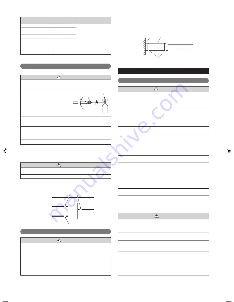
6.3.2. Bending pipes
The pipes are shaped by your hands. Be careful not to collapse them. Do not bend the
pipes in an angle more than 90°.
When pipes are repeatedly bent or stretched, the material will harden, making it dif
fi
cult
to bend or stretch them any more. Do not bend or stretch the pipes more than 3 times.
CAUTION
To prevent breaking of the pipe, avoid sharp bends. Bend the pipe with a radius of
curvature of 3-15/16 in (100 mm) or over.
If the pipe is bent repeatedly at the same place, it will break.
6.3.3. Pipe connection
Liquid pipe
Suction
gas pipe
unit
RB
Discharge
gas pipe
The pipe can be connected by brazing
Brazing
Brazing
RB
unit
6.4. Installing heat insulation
CAUTION
Insulate the suction gas pipe, discharge gas pipe, liquid pipe, and gas pipe with heat
insulation.
Use heat insulation with heat resistance above 248 °F (120 °C).
In addition, if the humidity level at the installation location of the refrigerant piping is
expected to exceed 70%, install heat insulation around the refrigerant piping. If the
expected humidity level is 70-80%, use heat insulation that is 9/16 in (15 mm) or
thicker and if the expected humidity exceeds 80%, use heat insulation that is 13/16 in
(20 mm) or thicker.
If heat insulation is used that is not as thick as speci
fi
ed, condensation may form on
the surface of the insulation. In addition, at 68 °F (20 °C), use heat insulation with
heat conductivity of 0.045 W/(m·K) or less.
6.4.1. Piping insulation
(1) After the sealing test is complete, carry out insulation work.
(2)
Insulate all pipes and piping connection parts so that there is no gap in it.
(3) Firmly connect the terminal part (a) so that no air comes in or out.
(4)
Do not squeeze the cable ties excessively so as to ensure that the insulation
material is thick.
(a)
Insulation (Locally purchased)
Cable tie (Locally purchased)
RB Unit
7. ELECTRICAL WIRING
7.1. Safety precautions for electrical wiring
WARNING
Electrical work must be performed in accordance with this Manual by a person
certi
fi
ed under the national or regional regulations. Be sure to use a dedicated circuit
for the unit.
An insufficient power supply circuit or improperly performed electrical work can
cause serious accidents such as electric shock or
fi
re.
Before starting work, check that power is not being supplied to the RB unit, indoor
unit and outdoor unit.
For wiring, use the prescribed type of cables, connect them securely, making sure
that there are no external forces of the cables applied to the terminal connections.
Improperly connected or secured cables can cause serious accidents such as
overheating the terminals, electric shock, or
fi
re.
Securely install the electrical box cover on the unit.
An improperly installed electrical box cover can cause serious accidents such as
electric shock or
fi
re through exposure to dust or water.
Use the included connection cables and power cables or ones specified by the
manufacturer. Improper connections, insufficient insulation, or exceeding the
allowable current can cause electric shock or
fi
re.
Do not modify the power cables, use extension cables, or use any branches in the
wiring. Improper connections, insufficient insulation, or exceeding the allowable
current can cause electric shock or
fi
re.
Match the terminal block numbers and connection cable colors with those of the
indoor unit or outdoor unit. Erroneous wiring may cause burning of the electric parts.
Securely connect the connection cables to the terminal board. In addition, secure
the cables with wiring holders. Improper connections, either in the wiring or at the
ends of the wiring, can cause a malfunction, electric shock, or
fi
re.
Always fasten the outside covering of the connection cable with the cable clamp. (If
the insulator is chafed, electric discharge may occur.)
We suggest installing GFEB breakers or follow local electrical code. When installing
this system, install using ground fault equipment breakers (GFEB) to reduce the risk
of leaking current which result in electric shock or potential
fi
re.
Always connect the earth (ground) cable.
Improper earthing (grounding) work can cause electric shocks.
Perform wiring work in accordance with standards so that the air conditioner can be
operated safely and positively.
If the supply cable is damaged, it must be replaced by the manufacturer, its service
agent or similarly quali
fi
ed persons in order to avoid a hazard.
CAUTION
Earth (Ground) the unit.
Do not connect the earth (ground) cable to a gas pipe, water pipe, lightning rod, or
a telephone earth (ground) cable.
Improper earthing (grounding) may cause electric shock.
Do not connect power supply cables to the transmission terminals, as this will
damage the product.
Never bundle the power supply cable and transmission cable, together.
Separate these cable by 2 in (50 mm) or more.
Bundling these cables together will cause miss operation or breakdown.
When handling PC board, static electricity charged in the body may cause
malfunction of the PC board. Follow the cautions below:
• Establish an earth (ground) for the RB units, indoor units, outdoor units and
peripheral devices.
• Cut power (breaker) off.
• Touch metal part of the RB units, indoor units and outdoor units for more than
10 seconds to discharge static electricity charged in the body.
• Do not touch terminals of parts and patterns implemented on PC board.
9366249030-05_IM.indb Sec1:7
9366249030-05_IM.indb Sec1:7
2015/2/26 13:11:33
2015/2/26 13:11:33


