


Trouble shooting 8 E14. 5
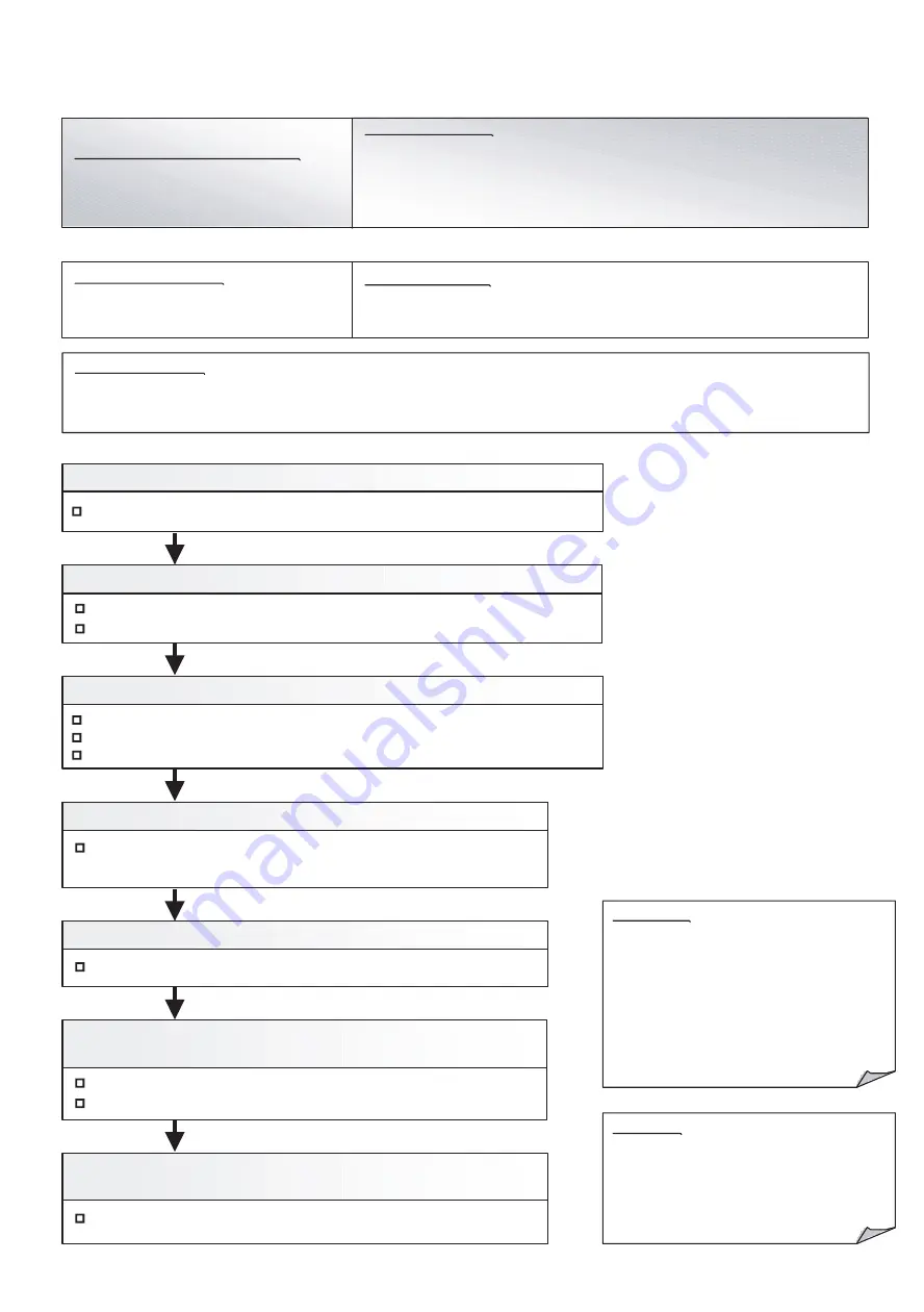
OUTDOOR UNIT Error Method:
The number of Indoor unit shortage
Error
Indicate or Display:
Outdoor Unit : E.1 4. 5
Error Code : 9 U / 1 4 / 1 6 / 1 4. 5 / 1 4. 3 *
Detective Actuators:
Outdoor unit Main PCB
Detective details:
When the indoor unit number decreases for 180 seconds from the memorized
maximum indoor units number after power(Breaker) ON.
Communication PCB connection check
Communication PCB check
Communication line connection, open check
Check Point 5 : Check the communication PCB
(indoor unit/ outdoor unit/ RB unit)
1. Indoor unit or RB unit power off 2. Noise, momentary open, voltage drop
3. Communication line connection defective 4. Terminal resistor setting mistake
5. Communication PCB mounting defective, Communication PCB defective
6. Controller PCB defective
Check Point 2 : Noise, momentary open, voltage drop
Check if temporary voltage drop was not generated.
Check if momentary open was not generated.
Check if ground is connection correctly or there are no related cables near the power line.
Check Point 2 : Check the indoor unit or RB unit power supply
Main power ON check
Power cable connection and open check
Check Point 3 : Check the communication line connection
Check Point 4 : Check the Terminal resistor setting
Terminal resistor setting check
Check Point 6 : Replace Main PCB and Communication PCB
(indoor unit/ outdoor unit/ RB unit)
Change Main PCB and Communication PCB, and set up the original address.
Forecast of Cause :
Check Point 1 : Find the indoor unit that the communication is lost.
Check system drawing and service tool.
OK
OK
OK
OK
OK
OK
Attention!!
In case of DIP-SW SET4-1 is ON(factory setting),
If this error occurs, system stops.In case of
DIP-SW SET4-1 is OFF,
If this error occurs, system does not stop.
If the failure indoor unit is pinpointed and it
needs to erase the error indication, it can be
reset by function setting (F3-41: Maximum
memorized indoor unit number reset).
Caution!!
Even if normal, this error occurs temporarily by
the timing of the power ON of outdoor unit,
indoor unit, RB unit, and signal amplifier.
In this case, please wait for 5 minutes after
turning on all the equipments.
Indoor Unit : Operation LED 9 times Flash, Timer LED 15 Times Flash,
Filter LED Continuous Flash. /
No display (When DIP-SW4-1 is OFF.)
Refer to SERVICE INFORMATION Network communication Abnormal
*Peripheral device indicates 14,16
04-17
Summary of Contents for Airstage UTP-RU01AH
Page 1: ...SERVICE MANUAL 208 230V 60Hz ...
Page 5: ...1 TEST RUN ...
Page 6: ......
Page 34: ...2 OUTDOOR UNIT OPERATION CONTROL ...
Page 59: ...3 INDOOR UNIT OPERATION ...
Page 60: ......
Page 82: ......
Page 83: ...4 TROUBLE SHOOTING ...
Page 84: ......
Page 186: ...04 96 0 24 AOUA120 208 230 AOUA72 90 0 19 RED WHITE BLACK U V W ...
Page 208: ...5 APPENDING DATA UNIT ...
Page 209: ......
Page 215: ...CASSETTE TYPE MODELS AUUB18TLAV AUUB24TLAV AUUB30TLAV AUUB36TLAV 05 06 ...
Page 217: ...MEDIUM STATIC PRESSURE DUCT TYPE MODEL ARUM24TLAV 05 08 MODEL ARUM30TLAV ARUM36TLAV ...
Page 218: ...HIGH STATIC PRESSURE DUCT TYPE MODELS ARUH36TLAV ARUH48TLAV ARUH60TLAV 05 09 ...
Page 219: ...FLOOR CEILING TYPE MODELS ABUA12TLAV ABUA14TLAV ABUA18TLAV ABUA24TLAV 05 10 ...
Page 220: ...CEILING TYPE MODELS ABUA30TLAV ABUA36TLAV INDOOR UNITS INDOOR UNITS 05 11 ...
Page 221: ...WALL MOUNTED TYPE MODELS ASUA7TLAV ASUA9TLAV ASUA12TLAV ASUA14TLAV 05 12 ...
Page 222: ...MODELS ASUB18TLAV ASUB24TLAV 05 13 ...
Page 224: ...MODEL UTP RU01AH MODEL UTP RU01BH 5 2 3 RB Unit 05 15 ...
Page 225: ...MODEL UTP RU01CH 05 16 ...
Page 226: ...MODEL UTP RU04BH 05 17 ...
Page 227: ...MODELS AAUA48TLAV 5 2 4 Outdoor Air Unit 05 18 MODELS AAUA72TLAV ...
Page 228: ...MODELS AAUA96TLAV 05 19 ...
Page 230: ...6 DISASSEMBLY PROCESS ...
Page 245: ......


