


01-06
Check Item
Check contents
Judgement
Present Status
Number of ref. circuit connected in the network system: ______, Ref. addresses: ______________(00 99)
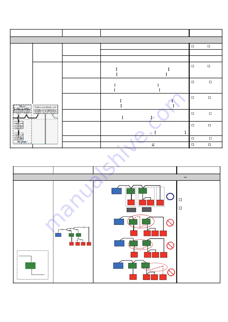
Transmission line
Transmission line layout
(Between RB unit & IU)
Correct
Not correct
If not correct, pls.
rectify the connection
Correct Layout
Not Correct Layout
Example - 1
Not Correct Layout
Example - 2
Not Correct Layout
Example - 3
RB
From outdoor
unit
To indoor
unit
Reference:
Reference:
(Piping Layout)
Check Item
Check contents
Judgement
Present Status
Number of ref. circuit connected in the network system: ______, Ref. addresses: ______________(00 - 99)
VRF
Network
System
Transmission wire
Outlook
Is it LonWorks compatible?
Yes / No
Maker name?
Wire specification
0.33mm
2
, shield wire
(AWG)
Transmission line
connection points
For cooling only IU
Between RB unit & IU
Must be properly connected (Between RB unit & IU)
RB unit Tterminal (OUT/U) : X1, X2, Earth
IU Terminal (IN/U) : X1, X2, Earth
Yes / No
For Heat Recovery IU
Between RB unit & IU
Must be properly connected (Between RB unit & IU)
RB unit Tterminal (IN/U) : X1, X2, Earth
IU Terminal (IN/U) : X1, X2, Earth
Yes / No
Between
RB unit & Master OU
Must be properly connected
(Between RB unit & Master OU)
RB unit Terminal (OUT/U) : X1, X2, Earth
Master OU Terminal (RB/U) : X1, X2, Earth
Yes / No
Between Master OUs
Must be properly connected (Between Master OUs)
Master OUs Terminal: Z1 & Z2
Yes / No
Between Master OU &
Slave OU or
In between Salve OUs
Must be properly connected (Between Master OU and
Slave OU / Slave OU and Slave OU )
Terminal: H1 & H2
Yes / No
Shield wire connection
Both ends of shield wire must be grounded
Yes / No
Wiring connection
Wiring connection per terminal ( 2)
Yes / No
OU
RB
IU
IU
IU
IU
RB
OU
RB
IU
IU
IU
IU
RB
OU
RB
IU
IU
IU
IU
RB
OU
RB
IU
IU
IU
IU
RB
RB Gr.
RB Gr.
OU
RB
IU
IU
IU
IU
RB
1-2-5 Transmission wire installation inspection sheet 1/3
Summary of Contents for Airstage UTP-RU01AH
Page 1: ...SERVICE MANUAL 208 230V 60Hz ...
Page 5: ...1 TEST RUN ...
Page 6: ......
Page 34: ...2 OUTDOOR UNIT OPERATION CONTROL ...
Page 59: ...3 INDOOR UNIT OPERATION ...
Page 60: ......
Page 82: ......
Page 83: ...4 TROUBLE SHOOTING ...
Page 84: ......
Page 186: ...04 96 0 24 AOUA120 208 230 AOUA72 90 0 19 RED WHITE BLACK U V W ...
Page 208: ...5 APPENDING DATA UNIT ...
Page 209: ......
Page 215: ...CASSETTE TYPE MODELS AUUB18TLAV AUUB24TLAV AUUB30TLAV AUUB36TLAV 05 06 ...
Page 217: ...MEDIUM STATIC PRESSURE DUCT TYPE MODEL ARUM24TLAV 05 08 MODEL ARUM30TLAV ARUM36TLAV ...
Page 218: ...HIGH STATIC PRESSURE DUCT TYPE MODELS ARUH36TLAV ARUH48TLAV ARUH60TLAV 05 09 ...
Page 219: ...FLOOR CEILING TYPE MODELS ABUA12TLAV ABUA14TLAV ABUA18TLAV ABUA24TLAV 05 10 ...
Page 220: ...CEILING TYPE MODELS ABUA30TLAV ABUA36TLAV INDOOR UNITS INDOOR UNITS 05 11 ...
Page 221: ...WALL MOUNTED TYPE MODELS ASUA7TLAV ASUA9TLAV ASUA12TLAV ASUA14TLAV 05 12 ...
Page 222: ...MODELS ASUB18TLAV ASUB24TLAV 05 13 ...
Page 224: ...MODEL UTP RU01AH MODEL UTP RU01BH 5 2 3 RB Unit 05 15 ...
Page 225: ...MODEL UTP RU01CH 05 16 ...
Page 226: ...MODEL UTP RU04BH 05 17 ...
Page 227: ...MODELS AAUA48TLAV 5 2 4 Outdoor Air Unit 05 18 MODELS AAUA72TLAV ...
Page 228: ...MODELS AAUA96TLAV 05 19 ...
Page 230: ...6 DISASSEMBLY PROCESS ...
Page 245: ......


