


01-07
Check Item
Check contents
Judgement
Present Status
Number of ref. circuit connected in the network system: ______, Ref. addresses: ______________(00 99)
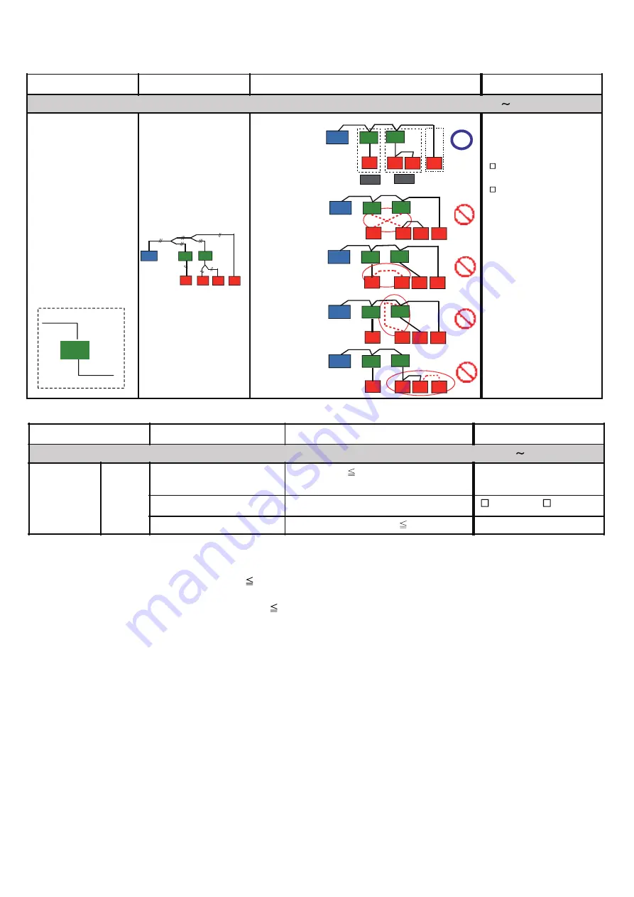
Transmission line
Transmission line layout
(Between RB unit & IU)
Correct
Not correct
If not correct, pls.
rectify the connection
Correct Layout
Not Correct Layout
Example - 1
Not Correct Layout
Example - 2
Not Correct Layout
Example - 3
Not Correct Layout
Example - 4
RB
From outdoor
unit
To indoor
unit
Reference:
Reference:
(Piping Layout)
Check Item
Check contents
Judgement
Present Status
Number of ref. circuit connected in the network system: ______, Ref. addresses:_______________(00
99)
VRF Network
System
Network
wiring
Total transmission line length
Wiring length 11811ft.(3600m)
(Value taken from Network Design Drawing)
(m)
Network wiring layout
Do not make a loop configuration
Looped / Not looped
No. of network segment
( * 1)
No. of network segment
41
( * 1)
Create one Network Segment based on the following conditions,
Condition -1: if the transmission line length
1640ft.(500m)
Condition -2: if a total number of connected units
64 connected units
( * 2)
( *
2
)
connected units mean a total of (Indoor Units + Master Outdoor Units + RB Units
( *
3
)
+ TPC Units + System Controller Units
Network Convertor for LonWorks Unit + Central RC Units + Network Convertor Units +
BACnet Gateway Unit + Signal Amplifier Units + Service Tool Unit + Web Monitoring Tool Unit)
(
3
)
for single type RB Unit, count as ‘0’, for multiple type RB Unit, when all ports are connected with Indoor Unit, count as ‘0’.
However, if one of the port of the multiple type RB Unit is not connected with Indoor Unit, at that time count as one RB Unit.
*
OU
RB
IU
IU
IU
IU
RB
OU
RB
IU
IU
IU
IU
RB
OU
RB
IU
IU
IU
IU
RB
OU
RB
IU
IU
IU
IU
RB
RB Gr.
RB Gr.
OU
RB
IU
IU
IU
IU
RB
OU
RB
IU
IU
RB
IU
IU
1-2-5 Transmission wire installation inspection sheet 2/3
Summary of Contents for Airstage UTP-RU01AH
Page 1: ...SERVICE MANUAL 208 230V 60Hz ...
Page 5: ...1 TEST RUN ...
Page 6: ......
Page 34: ...2 OUTDOOR UNIT OPERATION CONTROL ...
Page 59: ...3 INDOOR UNIT OPERATION ...
Page 60: ......
Page 82: ......
Page 83: ...4 TROUBLE SHOOTING ...
Page 84: ......
Page 186: ...04 96 0 24 AOUA120 208 230 AOUA72 90 0 19 RED WHITE BLACK U V W ...
Page 208: ...5 APPENDING DATA UNIT ...
Page 209: ......
Page 215: ...CASSETTE TYPE MODELS AUUB18TLAV AUUB24TLAV AUUB30TLAV AUUB36TLAV 05 06 ...
Page 217: ...MEDIUM STATIC PRESSURE DUCT TYPE MODEL ARUM24TLAV 05 08 MODEL ARUM30TLAV ARUM36TLAV ...
Page 218: ...HIGH STATIC PRESSURE DUCT TYPE MODELS ARUH36TLAV ARUH48TLAV ARUH60TLAV 05 09 ...
Page 219: ...FLOOR CEILING TYPE MODELS ABUA12TLAV ABUA14TLAV ABUA18TLAV ABUA24TLAV 05 10 ...
Page 220: ...CEILING TYPE MODELS ABUA30TLAV ABUA36TLAV INDOOR UNITS INDOOR UNITS 05 11 ...
Page 221: ...WALL MOUNTED TYPE MODELS ASUA7TLAV ASUA9TLAV ASUA12TLAV ASUA14TLAV 05 12 ...
Page 222: ...MODELS ASUB18TLAV ASUB24TLAV 05 13 ...
Page 224: ...MODEL UTP RU01AH MODEL UTP RU01BH 5 2 3 RB Unit 05 15 ...
Page 225: ...MODEL UTP RU01CH 05 16 ...
Page 226: ...MODEL UTP RU04BH 05 17 ...
Page 227: ...MODELS AAUA48TLAV 5 2 4 Outdoor Air Unit 05 18 MODELS AAUA72TLAV ...
Page 228: ...MODELS AAUA96TLAV 05 19 ...
Page 230: ...6 DISASSEMBLY PROCESS ...
Page 245: ......


