


OK
OK
OK
1. Driver PCB defective 2. Fan motor defective 3. Main PCB defective
4. Lose connection or disconnecting wire
Driver PCB
Fan motor
Main PCB
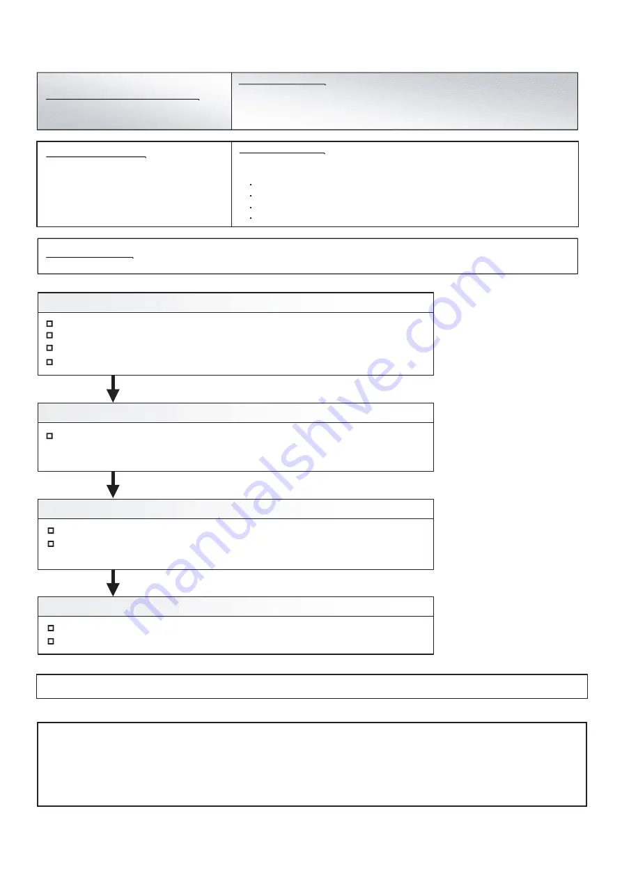
Check Point 1 : Check the wiring connection
Check Fan motor to Driver PCB wiring connector disconnection, open
Check Main PCB to Driver PCB wiring connector disconnection, open
Check Driver PCB to Capacitor wiring connector disconnection, open
Check Point 2 : Check DC input power of Driver PCB
Check the DC voltage of CN759 is within 15V+ 10%. Refer to the service parts info 5
>> If it is abnormal, replace Main PCB.
(When Main PCB is replaced, set up the original setting by Rotary, Dip, and Push SW)
Check Point 4 : Replace Fan motor
Indoor Unit : Operation LED 9 times Flash, Timer LED 15 Times Flash,
Filter LED Continuous Flash.
Outdoor Unit : E. 9 7. 9
Error Code : 9 U / 9 7
Outdoor Unit Fan Motor Driver
Abnormal
Trouble shooting 56 E97. 9
Indicate or Display:
Detective Actuators:
Detective details:
OUTDOOR UNIT Error Method:
Forecast of Cause :
When Driver PCB detects the following abnormalities,
the error signal is output.
Driver PCB defective
Fan motor defective (Layer short)
Main PCB defective (DC output abnormal)
Lose connection or disconnecting wire
Check the winding resistance of Fan motor.
Change Fan motor and check if the error reoccurs on a test run.
After fixing the problem and for canceling the Error, Error Reset (F3-40) will be required after power reset
-
Check Point 3 : Replace Driver PCB
Check the appearance and condition of mounting of Driver PCB.
Change Driver PCB and release the error.
Check if the error reoccurs on a test run.
Caution
By changing of DIP SW 4-2 to ON, the Back-up operation can start when the active outdoor unit exists on the multi outdoor unit connection.
(Stand alone outdoor unit is impossible)
The following conditions will be concerned in use of back-up operation. (Please do not use the system with back-up operation for long time.)
- The operating compressor life time becomes shorter.
- The operating performance may drop due to the limited active compressor(s).
- The compressor may stop frequently by protection controlling.
*In order to keep the operating capacity, the release of the Low noise mode setting might be necessary.
04-65
Check blown fuse of DC FAN motor (5A FUSE)
Summary of Contents for Airstage UTP-RU01AH
Page 1: ...SERVICE MANUAL 208 230V 60Hz ...
Page 5: ...1 TEST RUN ...
Page 6: ......
Page 34: ...2 OUTDOOR UNIT OPERATION CONTROL ...
Page 59: ...3 INDOOR UNIT OPERATION ...
Page 60: ......
Page 82: ......
Page 83: ...4 TROUBLE SHOOTING ...
Page 84: ......
Page 186: ...04 96 0 24 AOUA120 208 230 AOUA72 90 0 19 RED WHITE BLACK U V W ...
Page 208: ...5 APPENDING DATA UNIT ...
Page 209: ......
Page 215: ...CASSETTE TYPE MODELS AUUB18TLAV AUUB24TLAV AUUB30TLAV AUUB36TLAV 05 06 ...
Page 217: ...MEDIUM STATIC PRESSURE DUCT TYPE MODEL ARUM24TLAV 05 08 MODEL ARUM30TLAV ARUM36TLAV ...
Page 218: ...HIGH STATIC PRESSURE DUCT TYPE MODELS ARUH36TLAV ARUH48TLAV ARUH60TLAV 05 09 ...
Page 219: ...FLOOR CEILING TYPE MODELS ABUA12TLAV ABUA14TLAV ABUA18TLAV ABUA24TLAV 05 10 ...
Page 220: ...CEILING TYPE MODELS ABUA30TLAV ABUA36TLAV INDOOR UNITS INDOOR UNITS 05 11 ...
Page 221: ...WALL MOUNTED TYPE MODELS ASUA7TLAV ASUA9TLAV ASUA12TLAV ASUA14TLAV 05 12 ...
Page 222: ...MODELS ASUB18TLAV ASUB24TLAV 05 13 ...
Page 224: ...MODEL UTP RU01AH MODEL UTP RU01BH 5 2 3 RB Unit 05 15 ...
Page 225: ...MODEL UTP RU01CH 05 16 ...
Page 226: ...MODEL UTP RU04BH 05 17 ...
Page 227: ...MODELS AAUA48TLAV 5 2 4 Outdoor Air Unit 05 18 MODELS AAUA72TLAV ...
Page 228: ...MODELS AAUA96TLAV 05 19 ...
Page 230: ...6 DISASSEMBLY PROCESS ...
Page 245: ......


