


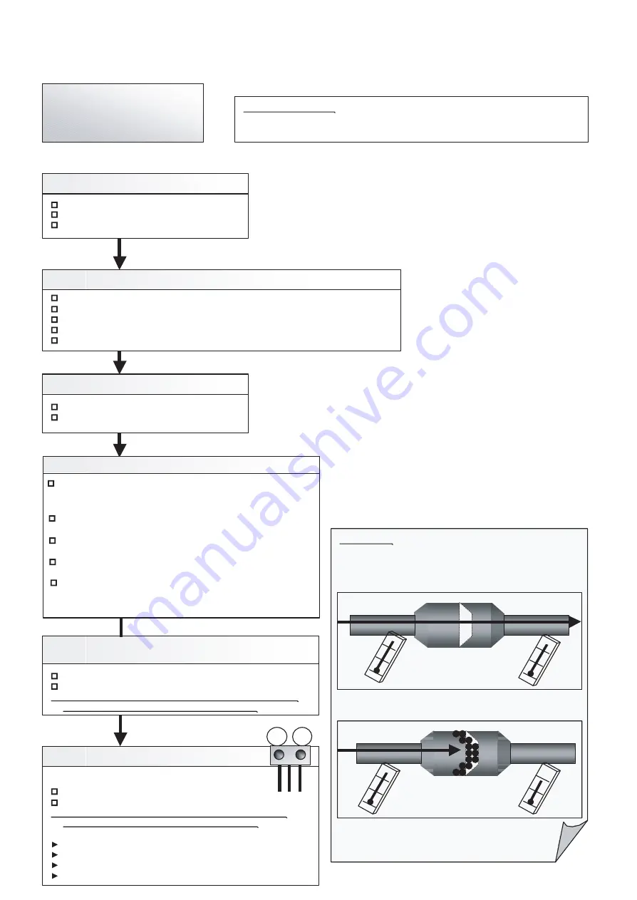
Attention!!
Strainer normally does not have temperature difference
between inlet and outlet as shown in (1), but if there is a
difference like shown in (2), there is a possibility of
inside clogged. In this case, replace Strainer.
Trouble shooting 77
No Cooling / No Heating
Check Point 2 : Check Outdoor Unit Operation
Check if Outdoor Unit is operating
Check any objects that obstruct the air flow route.
Check clogged Heat Exchanger.
Is the pipe length setting (Push Switch "MODE/EXIT", "SELECT", "ENTER") suitable?
Is the Valve open?
Check Point 1 : Check Indoor Unit
Does Indoor Unit FAN run on HIGH FAN?
Is Air Filter dirty?
Is Heat Exchanger clogged?
Check Point 3 : Check Site Condition
Is capacity of Indoor Unit fitted to Room size?
Any windows open? Or direct sunlight ?
Check Point 6 : Check Refrigeration Cycle
Check if Strainer is clogged (Refer to the figure at right).
Measure Gas Pressure and if there is a leakage, correct it.
>> When recharging the refrigerant, make sure to perform
vacuuming, and recharge the specified amount.
Check EEV (Refer to the Service Parts Information)
Check Solenoid Valve (Refer to the See Service Parts Information)
Check Compressor ( Refer to theSee Service Parts Information)
Check Point 5 :
Check Indoor/Outdoor Installation Condition
Check connection pipe (specified pipe length & Pipe diameter?)
Check any loose or removed communication line.
>> If there is an abnormal condition, correct it by referring to
Installation Manual or Design & Technical Manual.
Pipe (In)
Pipe (Out)
Pipe (In)
Pipe (Out)
(1)
(2)
OK
OK
OK
OK
PSI
PSI
Forecast of Cause :
1. Indoor Unit error 2. Outdoor Unit error 3. Effect by Surrounding environment
4. Connection Pipe / Connection Wire failure 5. Refrigeration cycle failure
Check Point 4 : RB Unit installation Condition
Check Error LED on RB Unit controller PCB
==> Wrong wire connection of Network cable
(Network cable for O.U. was installed on the terminal for I.U.)
Check wire connection between I.U. and applical terminal of RB unit.
==> Cross over connection, Lose connection
OK
Check Solenoid valve wrong connection on the PCB
==> Check the color of connector on the controller PCB
Check Solenoid valve defective
==> AC Power input and check the operation
Check pipe connection
==> Pipe Diameter, pipe length
Check 4 way valve ( Refer to theSee Service Parts Information)
>> If there is an abnormal condition, correct it by refering to
RB Unit Trouble shooting
04-86
Summary of Contents for Airstage UTP-RU01AH
Page 1: ...SERVICE MANUAL 208 230V 60Hz ...
Page 5: ...1 TEST RUN ...
Page 6: ......
Page 34: ...2 OUTDOOR UNIT OPERATION CONTROL ...
Page 59: ...3 INDOOR UNIT OPERATION ...
Page 60: ......
Page 82: ......
Page 83: ...4 TROUBLE SHOOTING ...
Page 84: ......
Page 186: ...04 96 0 24 AOUA120 208 230 AOUA72 90 0 19 RED WHITE BLACK U V W ...
Page 208: ...5 APPENDING DATA UNIT ...
Page 209: ......
Page 215: ...CASSETTE TYPE MODELS AUUB18TLAV AUUB24TLAV AUUB30TLAV AUUB36TLAV 05 06 ...
Page 217: ...MEDIUM STATIC PRESSURE DUCT TYPE MODEL ARUM24TLAV 05 08 MODEL ARUM30TLAV ARUM36TLAV ...
Page 218: ...HIGH STATIC PRESSURE DUCT TYPE MODELS ARUH36TLAV ARUH48TLAV ARUH60TLAV 05 09 ...
Page 219: ...FLOOR CEILING TYPE MODELS ABUA12TLAV ABUA14TLAV ABUA18TLAV ABUA24TLAV 05 10 ...
Page 220: ...CEILING TYPE MODELS ABUA30TLAV ABUA36TLAV INDOOR UNITS INDOOR UNITS 05 11 ...
Page 221: ...WALL MOUNTED TYPE MODELS ASUA7TLAV ASUA9TLAV ASUA12TLAV ASUA14TLAV 05 12 ...
Page 222: ...MODELS ASUB18TLAV ASUB24TLAV 05 13 ...
Page 224: ...MODEL UTP RU01AH MODEL UTP RU01BH 5 2 3 RB Unit 05 15 ...
Page 225: ...MODEL UTP RU01CH 05 16 ...
Page 226: ...MODEL UTP RU04BH 05 17 ...
Page 227: ...MODELS AAUA48TLAV 5 2 4 Outdoor Air Unit 05 18 MODELS AAUA72TLAV ...
Page 228: ...MODELS AAUA96TLAV 05 19 ...
Page 230: ...6 DISASSEMBLY PROCESS ...
Page 245: ......


