


Outdoor unit1
(Master unit)
IN/U
IN/U
RB unit
RB unit
Refrigerant piping
Dedicated cooling device
Transmission
Outdoor unit 2
(Slave unit 1)
Outdoor unit 3
(Slave unit 1)
Transmission
Transmission
Transmission
Transmission
IN/U
Transmission
Terminal -
Resistance
53 Ohm
< Main PCB >
-SET 5-4:ON-
Terminal Resistance
53 Ohm
<Main PCB>
-Internal circuit -
Terminal Resistance
53 Ohm
<Main PCB>
-Internal circuit -
Terminal Resistance
53 Ohm
<Main PCB>
-Internal circuit -
Transmission
Transmission
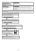
- Basic trouble shooting procedure -
1. Check Error code in one network segment separately, and check the Error code of (OU, IU, RB Error LED, RC, ST)
< If the system has more than 2 Net work segments, disconnect the other Network segment.>
2. Connect Service tool to the Outdoor unit, and try out
"Address checker"
Function by the Service toll.
< Check missing indoor unit or RB unit or outdoor unit by using Address checker function of Service tool>
3. Check terminal resistance value 53 Ohm + 5% + Line Resistance on the terminal borad one by one.
< Terminal Resistance is located on the Outdoor unit PCB(activated SET 5-4 ON), and the Main PCB of RB Unit each >
*Refer to the wiring diagram of Networlk cable
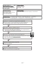
To other refrigerant circuit
Outdoor unit
A
B
C
D
Measurement
Terminal Resistance A
Measurement
Terminal Resistance A
Measurement
Terminal Resistance A
Measurement
Terminal Resistance B
Measurement
Terminal Resistance C
Measurement
Terminal Resistance D
4-3 SERVICE INFORMATION
SERVICE INFORMATION
Network communication Abnormal
Indoor Unit
Cooling Only
Indoor unit 4
Indoor unit 3
Indoor unit 2
Indoor unit 1
Terminal Resistance A is located on the controller PCB of Outdoor unit as the Network for RB unit, Cooling only Indoor unit
Terminal Resistance B is located on the Main PCB of RB unit as the Network for Indoor unit 1
Terminal Resistance C is located on the Main PCB of RB unit as the Network for Indoor unit 2
Terminal Resistance D is located on the Main PCB of RB unit as the Network for Indoor unit 3 and Indoor unit 4
-
Exsample
04-89
Summary of Contents for Airstage UTP-RU01AH
Page 1: ...SERVICE MANUAL 208 230V 60Hz ...
Page 5: ...1 TEST RUN ...
Page 6: ......
Page 34: ...2 OUTDOOR UNIT OPERATION CONTROL ...
Page 59: ...3 INDOOR UNIT OPERATION ...
Page 60: ......
Page 82: ......
Page 83: ...4 TROUBLE SHOOTING ...
Page 84: ......
Page 186: ...04 96 0 24 AOUA120 208 230 AOUA72 90 0 19 RED WHITE BLACK U V W ...
Page 208: ...5 APPENDING DATA UNIT ...
Page 209: ......
Page 215: ...CASSETTE TYPE MODELS AUUB18TLAV AUUB24TLAV AUUB30TLAV AUUB36TLAV 05 06 ...
Page 217: ...MEDIUM STATIC PRESSURE DUCT TYPE MODEL ARUM24TLAV 05 08 MODEL ARUM30TLAV ARUM36TLAV ...
Page 218: ...HIGH STATIC PRESSURE DUCT TYPE MODELS ARUH36TLAV ARUH48TLAV ARUH60TLAV 05 09 ...
Page 219: ...FLOOR CEILING TYPE MODELS ABUA12TLAV ABUA14TLAV ABUA18TLAV ABUA24TLAV 05 10 ...
Page 220: ...CEILING TYPE MODELS ABUA30TLAV ABUA36TLAV INDOOR UNITS INDOOR UNITS 05 11 ...
Page 221: ...WALL MOUNTED TYPE MODELS ASUA7TLAV ASUA9TLAV ASUA12TLAV ASUA14TLAV 05 12 ...
Page 222: ...MODELS ASUB18TLAV ASUB24TLAV 05 13 ...
Page 224: ...MODEL UTP RU01AH MODEL UTP RU01BH 5 2 3 RB Unit 05 15 ...
Page 225: ...MODEL UTP RU01CH 05 16 ...
Page 226: ...MODEL UTP RU04BH 05 17 ...
Page 227: ...MODELS AAUA48TLAV 5 2 4 Outdoor Air Unit 05 18 MODELS AAUA72TLAV ...
Page 228: ...MODELS AAUA96TLAV 05 19 ...
Page 230: ...6 DISASSEMBLY PROCESS ...
Page 245: ......


