


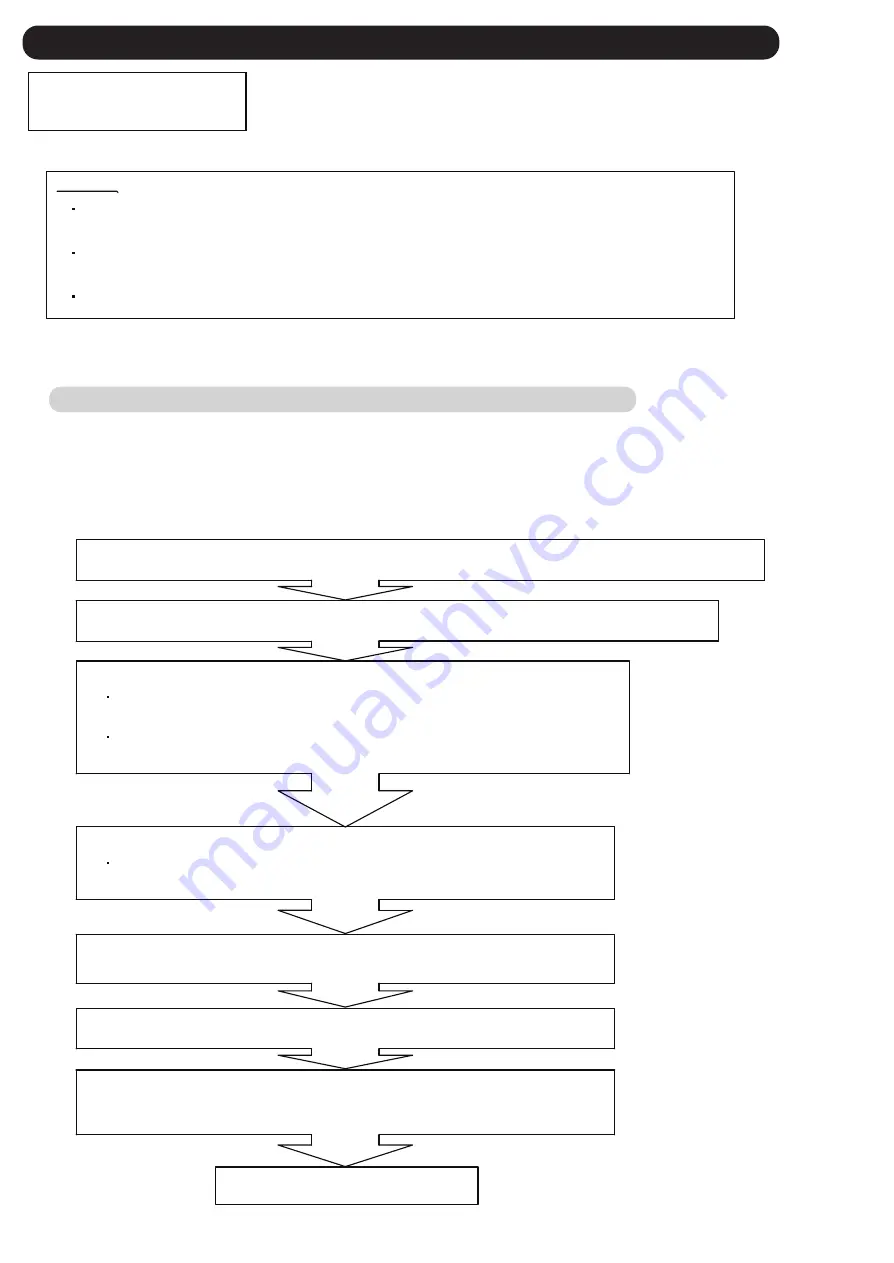
1. Stop the operation, and turn off the all outdoor units.
1-1. Backup operation when compressor of the master unit is defective.
[Procedure]
(Example: Three outdoor units are connected.)
2. Fully shut off the 3-way valve (Liquid, High pressure gas, Low pressure gas) of the broken master unit.
3. Set the
Slave unit #1
as a new master unit, and make up the system of two outdoor units.
5. Uncouple the transmission connector between the broken master unit and indoor units,
and connect it into the slave unit #1 (substitutional master unit).
7. Turn on the units except the broken master unit, and wait for more than 30 seconds.
(Do not turn on the broken master unit)
8. It is ready for Backup operation.
Start operation as usual.
1. Method of backup operation
SERVICE INFORMATION
Backup Operation
4-4 SERVICE INFORMATION
Backup operation is the operating method of replacing compressor while the system is running.
Compressor can be replaced without stopping the system.
Details :
In backup operation, cooling and heating capacity is decreased by the capacity
of the separated outdoor unit.
The work procedure is as follows.
Change the setting of the DIP SW 3-1 / 3-2 (Outdoor unit address setting) of the slave
unit #1, from [ ](slave unit #1) to [ ](
Master unit
).
Change the setting of the DIP SW 3-3 / 3-4 (Number of slave units connected setting)
of the slave unit #1, from [ ](zero unit) to [ ](one unit).
6. Change the setting of the DIP SW 5-1/ 5-2 (Number of outdoor unit) of the slave unit #1 (substitutional
master unit) and #2 (substitutional slave unit #1), from [ON/ OFF](3) to [OFF/ ON](2).
4. Set up the
Slave unit #2
as the slave unit #1.
Change the DIP SW 3-1/ 3-2 (Outdoor unit address setting) of the slave unit #2,
from [ON/ OFF](slave unit #2) to [OFF/ ON](
Slave unit #1
).
4-4-1 Backup operation
OFF / ON
OFF / OFF
OFF / OFF
OFF / ON
( Make sure the pressure equalization has been finished.)
04-91
Summary of Contents for Airstage UTP-RU01AH
Page 1: ...SERVICE MANUAL 208 230V 60Hz ...
Page 5: ...1 TEST RUN ...
Page 6: ......
Page 34: ...2 OUTDOOR UNIT OPERATION CONTROL ...
Page 59: ...3 INDOOR UNIT OPERATION ...
Page 60: ......
Page 82: ......
Page 83: ...4 TROUBLE SHOOTING ...
Page 84: ......
Page 186: ...04 96 0 24 AOUA120 208 230 AOUA72 90 0 19 RED WHITE BLACK U V W ...
Page 208: ...5 APPENDING DATA UNIT ...
Page 209: ......
Page 215: ...CASSETTE TYPE MODELS AUUB18TLAV AUUB24TLAV AUUB30TLAV AUUB36TLAV 05 06 ...
Page 217: ...MEDIUM STATIC PRESSURE DUCT TYPE MODEL ARUM24TLAV 05 08 MODEL ARUM30TLAV ARUM36TLAV ...
Page 218: ...HIGH STATIC PRESSURE DUCT TYPE MODELS ARUH36TLAV ARUH48TLAV ARUH60TLAV 05 09 ...
Page 219: ...FLOOR CEILING TYPE MODELS ABUA12TLAV ABUA14TLAV ABUA18TLAV ABUA24TLAV 05 10 ...
Page 220: ...CEILING TYPE MODELS ABUA30TLAV ABUA36TLAV INDOOR UNITS INDOOR UNITS 05 11 ...
Page 221: ...WALL MOUNTED TYPE MODELS ASUA7TLAV ASUA9TLAV ASUA12TLAV ASUA14TLAV 05 12 ...
Page 222: ...MODELS ASUB18TLAV ASUB24TLAV 05 13 ...
Page 224: ...MODEL UTP RU01AH MODEL UTP RU01BH 5 2 3 RB Unit 05 15 ...
Page 225: ...MODEL UTP RU01CH 05 16 ...
Page 226: ...MODEL UTP RU04BH 05 17 ...
Page 227: ...MODELS AAUA48TLAV 5 2 4 Outdoor Air Unit 05 18 MODELS AAUA72TLAV ...
Page 228: ...MODELS AAUA96TLAV 05 19 ...
Page 230: ...6 DISASSEMBLY PROCESS ...
Page 245: ......


