


SERVICE PARTS INFORMATION 3
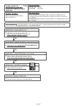
Main PCB
Filter PCB (Main)
Check Filter PCB (Main) -2
Check Filter PCB (Main) -1
Check Filter PCB (Main) -3
Replace Main PCB
Replace Main PCB
YES
YES
Check Main PCB -1
Replace Filter PCB (Main)
Replace Filter PCB (Main)
NO
YES
YES
Electric parts check
NO
Replace defective electric parts
YES
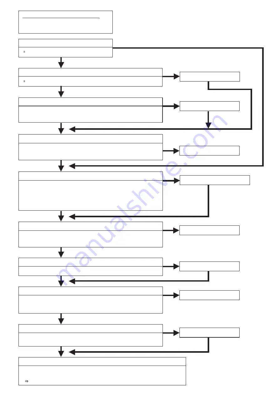
PCB pattern and parts on PCB defective?
Is Fuse (5A/ 250V) open?
(1) Replace blown fuse.
(2) Disconnect all the connection wires between the Filter PCB (Main) - Main PCB.
(3) Is there a short between L1-N, L3-N, and L1-L3?
(4) Connect all the connection wires between the Filter PCB (Main) - Main PCB
disconnected at step (2).
(5) The same as step (3), is there a short between L1-N, L3-N, and L1-L3?
(6) Are the following parts defective?
*For the check method, refer to 6-5.
- EEV 1~4
- SV 1~4
- 4-way valve
- Pressure sensor (High pressure/ Low pressure)
Check Main PCB -3
NO
NO
Check Main PCB -2
YES
(7) Disconnect the wires of the pressure sensors(High pressure/ Low pressure)
connected to the connector of the Main PCB.
(8) Is there a short between pins 1-3 of the Main PCB side connector?
(9) Is there a short between pins 1-6 of CN161?
Replace Main PCB
YES
Replace Main PCB
YES
NO
NO
NO
NO
Check Main PCB -4
(10) Disconnect the Main PCB side connector of the connection wires
(8-pin connector) between the Main PCB - Inverter PCB.
(11) Is there a short between pins 1-2 of the Main PCB side connector (8 pins)?
Turn on the power.
(12) Reconnect all the connection wires disconnected up to (1)-(11) to their original places.
(13) Turn on the AC power.
If the LED of the Main PCB does not light or blink, replaces the Main PCB, Filter PCB (Main).
Replace Main PCB
YES
NO
Check Main PCB -5
(12) Disconnect the Main PCB side connector of the connection wires
(6-pin connector) between the Main PCB - Fan PCB.
04-97
Summary of Contents for Airstage UTP-RU01AH
Page 1: ...SERVICE MANUAL 208 230V 60Hz ...
Page 5: ...1 TEST RUN ...
Page 6: ......
Page 34: ...2 OUTDOOR UNIT OPERATION CONTROL ...
Page 59: ...3 INDOOR UNIT OPERATION ...
Page 60: ......
Page 82: ......
Page 83: ...4 TROUBLE SHOOTING ...
Page 84: ......
Page 186: ...04 96 0 24 AOUA120 208 230 AOUA72 90 0 19 RED WHITE BLACK U V W ...
Page 208: ...5 APPENDING DATA UNIT ...
Page 209: ......
Page 215: ...CASSETTE TYPE MODELS AUUB18TLAV AUUB24TLAV AUUB30TLAV AUUB36TLAV 05 06 ...
Page 217: ...MEDIUM STATIC PRESSURE DUCT TYPE MODEL ARUM24TLAV 05 08 MODEL ARUM30TLAV ARUM36TLAV ...
Page 218: ...HIGH STATIC PRESSURE DUCT TYPE MODELS ARUH36TLAV ARUH48TLAV ARUH60TLAV 05 09 ...
Page 219: ...FLOOR CEILING TYPE MODELS ABUA12TLAV ABUA14TLAV ABUA18TLAV ABUA24TLAV 05 10 ...
Page 220: ...CEILING TYPE MODELS ABUA30TLAV ABUA36TLAV INDOOR UNITS INDOOR UNITS 05 11 ...
Page 221: ...WALL MOUNTED TYPE MODELS ASUA7TLAV ASUA9TLAV ASUA12TLAV ASUA14TLAV 05 12 ...
Page 222: ...MODELS ASUB18TLAV ASUB24TLAV 05 13 ...
Page 224: ...MODEL UTP RU01AH MODEL UTP RU01BH 5 2 3 RB Unit 05 15 ...
Page 225: ...MODEL UTP RU01CH 05 16 ...
Page 226: ...MODEL UTP RU04BH 05 17 ...
Page 227: ...MODELS AAUA48TLAV 5 2 4 Outdoor Air Unit 05 18 MODELS AAUA72TLAV ...
Page 228: ...MODELS AAUA96TLAV 05 19 ...
Page 230: ...6 DISASSEMBLY PROCESS ...
Page 245: ......


