


2-8 SPECIAL OPERATION
(1) Purpose of the operation
The amount of refrigerant lubricant oil which has been transported to the indoor units
and the connection pipe with the refrigerant will become large as the operation time of compressor increases.
It is necessary to recover the oil back into the outdoor unit for a certain time interval
in order to prevent compressors from damaging due to lack of lubrication oil.
During the oil recovery operation, the status can confirm:
appears on the display
- 3 wires WRC and Central remote controller ---
appears on the display
- Simple remote controller ---
.
Others
02-11
< Start condition >
< End condition >
Compressor accumulated operation time since last oil recovery operation exceeds 3 hours
(first time: 1 hour.)
3 minutes have elapsed since the compressor restart and Suction superheat "Suction temperature - Lowpressure
saturaion temperature" 10 F (5 C) at all Outdoor units
Or
6 minutes have elapsed since the start
< Operation >
Compressor
Heat Ex(4WV)
FAN
Heat Ex EEV
SV1,SV2
All compressor operation Stop
Keeps the operation mode
Stops
0 pls
Open
All compressor start
Condensor (OFF)
Start (Target high pressure control)
480pls
Close
All compressor operation Stop
Keeps the operation mode
Stops
0 pls
Open
Preparation process
On Oil recovery operatiom
Finishing process
Actuator
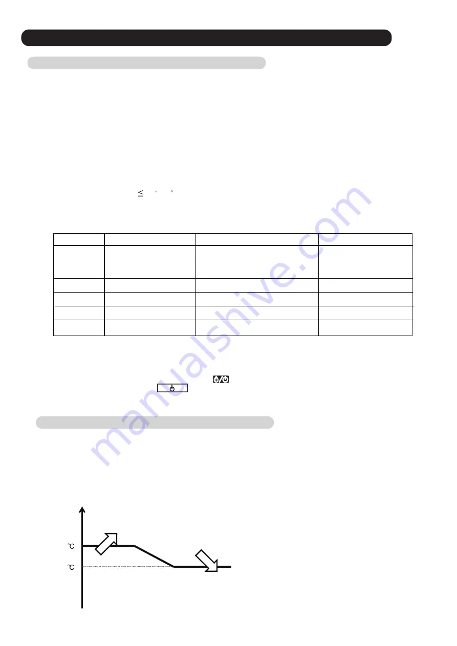
2-8-2 Pre-heat operation
This pre-heat operation protects the start up failure by preventing the refrigerant from soaking into the oil in compressor.
Crankcase heater ON: 30 minutes elapsed since installed compressors stopped (However, ON when power turned on)
OFF: Installed compressors operation
35W (1 pcs)
70W (2 pcs)
5
3
2 pcs of belt heater installed on the compressor
The crankcase heaters are controlled by the outdoor temperature
< Control condition >
- 2 wires WRC --- Press the Status button on the screen.
- LED indication --- Operation LED (Green) flash slowly.
2-8-1 Oil Recovery operation
Summary of Contents for Airstage UTP-RU01AH
Page 1: ...SERVICE MANUAL 208 230V 60Hz ...
Page 5: ...1 TEST RUN ...
Page 6: ......
Page 34: ...2 OUTDOOR UNIT OPERATION CONTROL ...
Page 59: ...3 INDOOR UNIT OPERATION ...
Page 60: ......
Page 82: ......
Page 83: ...4 TROUBLE SHOOTING ...
Page 84: ......
Page 186: ...04 96 0 24 AOUA120 208 230 AOUA72 90 0 19 RED WHITE BLACK U V W ...
Page 208: ...5 APPENDING DATA UNIT ...
Page 209: ......
Page 215: ...CASSETTE TYPE MODELS AUUB18TLAV AUUB24TLAV AUUB30TLAV AUUB36TLAV 05 06 ...
Page 217: ...MEDIUM STATIC PRESSURE DUCT TYPE MODEL ARUM24TLAV 05 08 MODEL ARUM30TLAV ARUM36TLAV ...
Page 218: ...HIGH STATIC PRESSURE DUCT TYPE MODELS ARUH36TLAV ARUH48TLAV ARUH60TLAV 05 09 ...
Page 219: ...FLOOR CEILING TYPE MODELS ABUA12TLAV ABUA14TLAV ABUA18TLAV ABUA24TLAV 05 10 ...
Page 220: ...CEILING TYPE MODELS ABUA30TLAV ABUA36TLAV INDOOR UNITS INDOOR UNITS 05 11 ...
Page 221: ...WALL MOUNTED TYPE MODELS ASUA7TLAV ASUA9TLAV ASUA12TLAV ASUA14TLAV 05 12 ...
Page 222: ...MODELS ASUB18TLAV ASUB24TLAV 05 13 ...
Page 224: ...MODEL UTP RU01AH MODEL UTP RU01BH 5 2 3 RB Unit 05 15 ...
Page 225: ...MODEL UTP RU01CH 05 16 ...
Page 226: ...MODEL UTP RU04BH 05 17 ...
Page 227: ...MODELS AAUA48TLAV 5 2 4 Outdoor Air Unit 05 18 MODELS AAUA72TLAV ...
Page 228: ...MODELS AAUA96TLAV 05 19 ...
Page 230: ...6 DISASSEMBLY PROCESS ...
Page 245: ......


