


02-20
Protective function
Detect device
Operation
Cool Heat
Low pressure
protection 1
Low pressure
sensor
Abnormal low
pressure
protection
control
Low pressure
sensor
Low pressure
protection stop
Low pressure
sensor
Low pressure
sensor
Low pressure
protection 2
Low pressure
protection 3
Low pressure
sensor
Display
P3
EA51
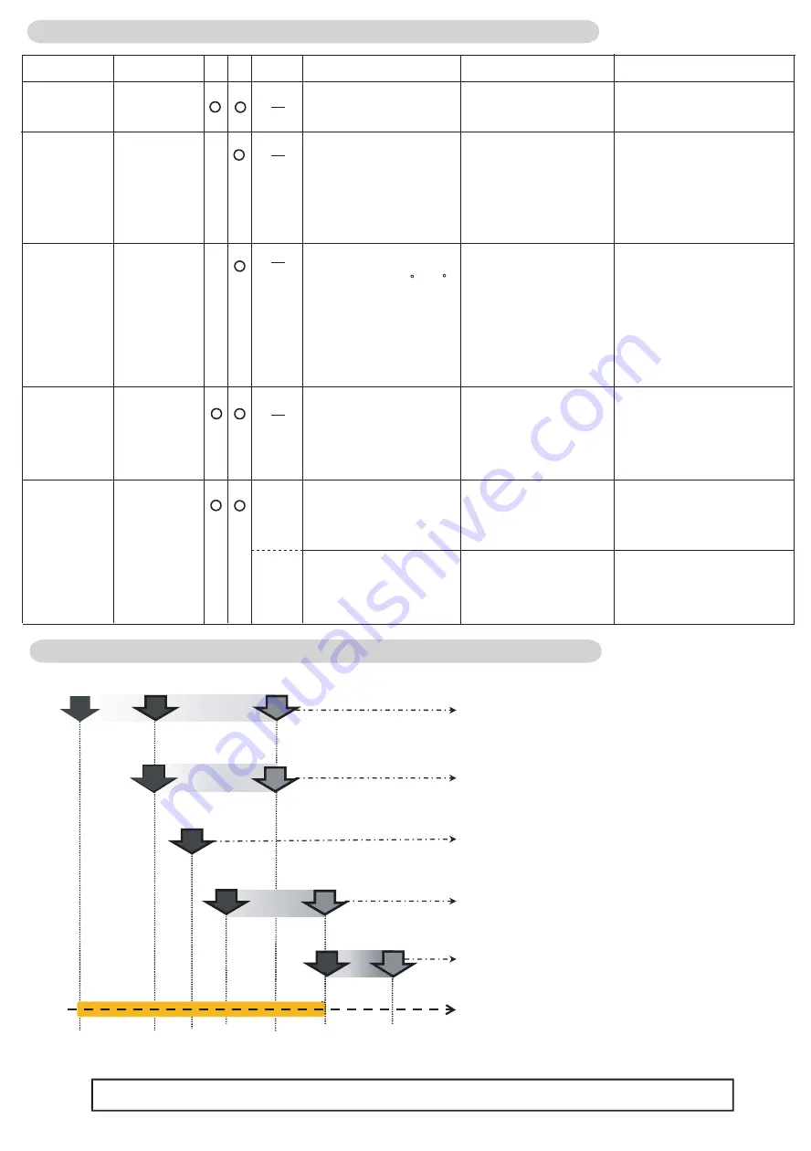
2-9-3 Low pressure protection
Start condition
Release condition
Below 15psi (0.10MPa)
3minutes elapsed and
Above 25psi (0.17MPa)
SV1 =>ON
After compressor started
and 3 minutes elapsed
and Below 94psi (0.18MPa)
3minutes elapsed and
above 32psi (0.22MPa)
Operating Indoor unit EEV
forced controlling
-Thermo-OFF indoor unit:
450pls.
-Thermo-ON indoor unit:
gradually opens.
Below 19psi (0.13MPa)
and SH* above 50 F (10 C)
and EEV1 (EEV2) is oper-
ating with less than 52pls.
*SH = Heat-Ex1(2) Gas
temp - Low pressure
saturation temp.
Except the start condition
EEV1 (EEV2) set 52 plus
Below 23psi (0.16MPa)
3minutes elapsed and
above 94psi (0.18MPa)
Compressor rotation speed
lessen in the limited time until
above 25psi (0.17Mpa)
(Compressor rotation speed
rise up prohibit)
Pattern 1
Below 7psi (0.05MPa) or
15psi (0.10MPa) for 10min.
3minutes elapsed and
Above 25psi (0.17Mpa)
Corresponding outdoor unit
stops
Pattern 2
Pattern 1 generated 5
times within 180 minutes
Error reset (push button
SW) executed after power
turned on
Corresponding outdoor unit
stops (Permanent stop) &
Error display
R
S
R
*
LPP Stop : Error Indication E A 51
* for a 10 Minutes
Protection controlling range in cooling / heating operaing mode
R
S
R
S
R
LP Protection1 : SV1 ON
LP protection 3: EEV1(2) set as 52 pls
*When EEV puls is less than 52 pls.
(Only heating/Heating Main)
Abnormal LP protection :
Compressor rotation speed forced cntrolling
LP Protection2 :
Indoor unit (Heating/ Thermo OFF) EEV
S
7 15 19 23 25 94 32 (psi)
foced controlling
Note: Target pressure controlling will be cancelled when the operating pressure is in the range of orange.
S
Low pressure protection - Summary -
0.05 0.10 0.13 0.16 0.17 0.18 0.22 (
MPa
)
Summary of Contents for Airstage UTP-RU01AH
Page 1: ...SERVICE MANUAL 208 230V 60Hz ...
Page 5: ...1 TEST RUN ...
Page 6: ......
Page 34: ...2 OUTDOOR UNIT OPERATION CONTROL ...
Page 59: ...3 INDOOR UNIT OPERATION ...
Page 60: ......
Page 82: ......
Page 83: ...4 TROUBLE SHOOTING ...
Page 84: ......
Page 186: ...04 96 0 24 AOUA120 208 230 AOUA72 90 0 19 RED WHITE BLACK U V W ...
Page 208: ...5 APPENDING DATA UNIT ...
Page 209: ......
Page 215: ...CASSETTE TYPE MODELS AUUB18TLAV AUUB24TLAV AUUB30TLAV AUUB36TLAV 05 06 ...
Page 217: ...MEDIUM STATIC PRESSURE DUCT TYPE MODEL ARUM24TLAV 05 08 MODEL ARUM30TLAV ARUM36TLAV ...
Page 218: ...HIGH STATIC PRESSURE DUCT TYPE MODELS ARUH36TLAV ARUH48TLAV ARUH60TLAV 05 09 ...
Page 219: ...FLOOR CEILING TYPE MODELS ABUA12TLAV ABUA14TLAV ABUA18TLAV ABUA24TLAV 05 10 ...
Page 220: ...CEILING TYPE MODELS ABUA30TLAV ABUA36TLAV INDOOR UNITS INDOOR UNITS 05 11 ...
Page 221: ...WALL MOUNTED TYPE MODELS ASUA7TLAV ASUA9TLAV ASUA12TLAV ASUA14TLAV 05 12 ...
Page 222: ...MODELS ASUB18TLAV ASUB24TLAV 05 13 ...
Page 224: ...MODEL UTP RU01AH MODEL UTP RU01BH 5 2 3 RB Unit 05 15 ...
Page 225: ...MODEL UTP RU01CH 05 16 ...
Page 226: ...MODEL UTP RU04BH 05 17 ...
Page 227: ...MODELS AAUA48TLAV 5 2 4 Outdoor Air Unit 05 18 MODELS AAUA72TLAV ...
Page 228: ...MODELS AAUA96TLAV 05 19 ...
Page 230: ...6 DISASSEMBLY PROCESS ...
Page 245: ......


