


02-21
Protective function Detect device
Operation
Cool Heat
Heatsink temp
sensor
Heatsink temp
sensor
Heatsink temp
sensor
Heatsink temp
sensor
Heatsink
temperature
protection stop
Display
EAC4
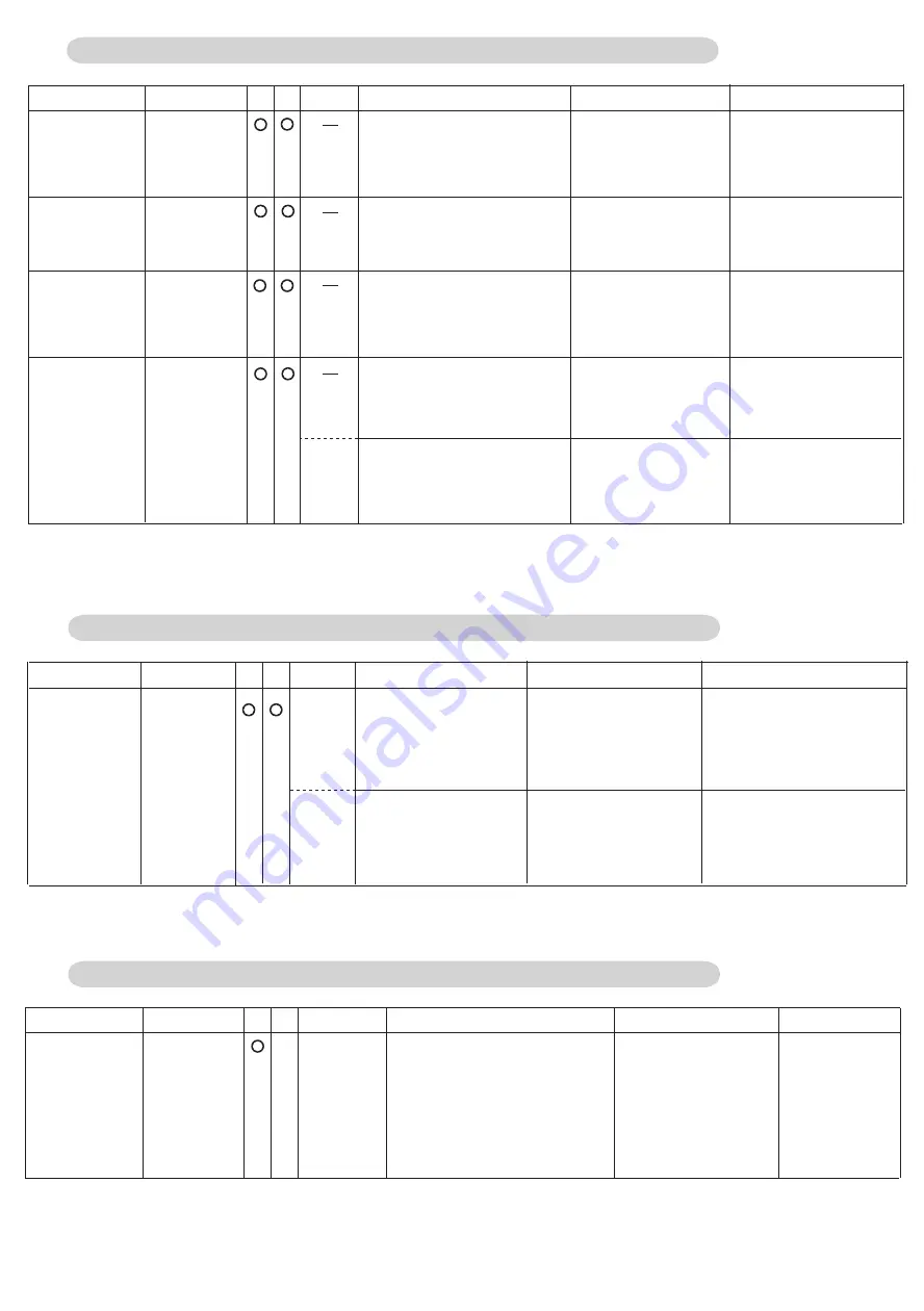
2-9-4 Heatsink temperature protection
Start condition
Release condition
Above 167
°F (
75
°C)
Below 167
°F (75°C)
Cancel Fan speed
step down.
Heat sink
temperature
protection 1
Heat sink
temperature
protection 2
Compressor rotation speed
lessens- 10 rps/ 120sec.
Heat sink
temperature
protection 3
Above 181
°F
(83
°C
)
Above 189
°F (87°C)
Below 181
°F (83°C)
Fan speed up 1 step
every 2 minutes.
(Pattern 1
Above 196
°F (91°C))
Pattern 2
Pattern 1 generated 3
times within 60 minutes
3 minutes elapsed,
and below 167
°F(75°C)
10 minutes elapsed,
and below 167
°F(75°C)
Compressor stops
Compressor stop
and Error indication.
Protective function Detect device
Operation
Cool Heat
Display
Compressor
temperature
protection stop
Compressor
temp.
sensor
<TH11>
EA31
P4
2-9-5 Compressor temperature protection
Start condition
Release condition
Pattern 1
Compressor temperature
above 239
°F(115°C)
3 minutes have elapsed
and Discharge temp.
below 176
°F(80°C)
Corresponding outdoor
unit stops
Pattern 2
Pattern 1 generated 2
times within 40 minutes
Error reset (push button
SW) executed after
power reset.
Corresponding outdoor
unit stops (Permanent
stop) & Error display
2-9-6 O.U Heat - Ex.1(2) Gas Temp. abnormal stop
Protective function Detect device
Operation
Cool Heat
Display
Start condition
Release condition
Heat-Ex 1(2)
Gas temp.
Sensor
<TH7,TH8>
EA63
(Heat Ex1)
Heat Ex.1(2) gas temp. sensor
TH7 (TH8) for use as condenser
(4Way valve: Off, EEV: Open) is
detected abnormally-low to High
pressure saturated temp. for 4
minutes or more.
Error reset (push button
SW) executed after
power turned on
System Stop and
Error indication
O.U Heat - Ex.
1(2) Gas Temp.
abnormal stop
EA64
(Heat Ex2)
Below 167
°F (75°C)
Summary of Contents for Airstage UTP-RU01AH
Page 1: ...SERVICE MANUAL 208 230V 60Hz ...
Page 5: ...1 TEST RUN ...
Page 6: ......
Page 34: ...2 OUTDOOR UNIT OPERATION CONTROL ...
Page 59: ...3 INDOOR UNIT OPERATION ...
Page 60: ......
Page 82: ......
Page 83: ...4 TROUBLE SHOOTING ...
Page 84: ......
Page 186: ...04 96 0 24 AOUA120 208 230 AOUA72 90 0 19 RED WHITE BLACK U V W ...
Page 208: ...5 APPENDING DATA UNIT ...
Page 209: ......
Page 215: ...CASSETTE TYPE MODELS AUUB18TLAV AUUB24TLAV AUUB30TLAV AUUB36TLAV 05 06 ...
Page 217: ...MEDIUM STATIC PRESSURE DUCT TYPE MODEL ARUM24TLAV 05 08 MODEL ARUM30TLAV ARUM36TLAV ...
Page 218: ...HIGH STATIC PRESSURE DUCT TYPE MODELS ARUH36TLAV ARUH48TLAV ARUH60TLAV 05 09 ...
Page 219: ...FLOOR CEILING TYPE MODELS ABUA12TLAV ABUA14TLAV ABUA18TLAV ABUA24TLAV 05 10 ...
Page 220: ...CEILING TYPE MODELS ABUA30TLAV ABUA36TLAV INDOOR UNITS INDOOR UNITS 05 11 ...
Page 221: ...WALL MOUNTED TYPE MODELS ASUA7TLAV ASUA9TLAV ASUA12TLAV ASUA14TLAV 05 12 ...
Page 222: ...MODELS ASUB18TLAV ASUB24TLAV 05 13 ...
Page 224: ...MODEL UTP RU01AH MODEL UTP RU01BH 5 2 3 RB Unit 05 15 ...
Page 225: ...MODEL UTP RU01CH 05 16 ...
Page 226: ...MODEL UTP RU04BH 05 17 ...
Page 227: ...MODELS AAUA48TLAV 5 2 4 Outdoor Air Unit 05 18 MODELS AAUA72TLAV ...
Page 228: ...MODELS AAUA96TLAV 05 19 ...
Page 230: ...6 DISASSEMBLY PROCESS ...
Page 245: ......


